Why half the motor command is not half the speed: drivers and feedback
Separate a motor command from measured speed. Learn the roles of drivers and feedback, convert encoder counts to RPM, and work through a practical reasoning exercise.
Contents
A 50% motor command does not mean half the maximum speed. It commonly specifies how much of each switching cycle the driver applies a particular output state. Actual speed also depends on the motor, supply and mechanical load. To maintain a chosen speed, measure the motion, compare it with the target and adjust the command using the difference. Returning information about the result is called feedback.
Imagine a small robot wheel that turns freely on a bench but slows down on carpet. A program that keeps sending the same command has no direct evidence of that slowdown. This lesson separates the part that supplies motor power, the part that makes decisions and the measurement that tells us what happened.
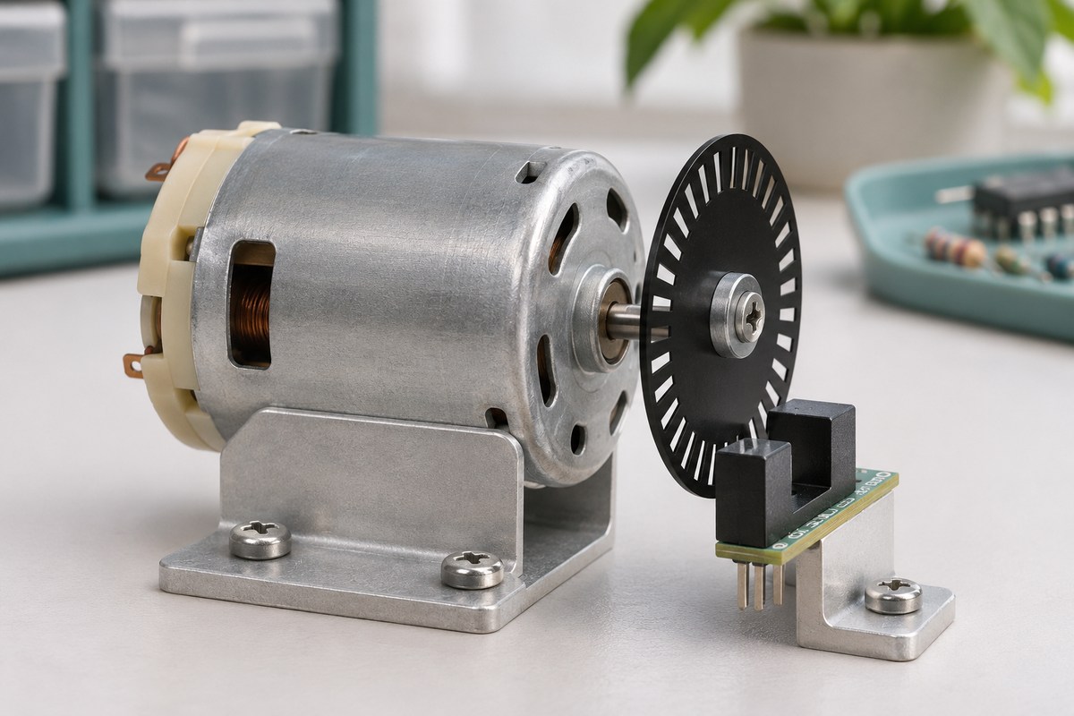
Command, power and measurement are different roles
A microcontroller is the device that runs the control program. Its output can request movement, but it is not intended to supply a motor's operating current directly. A motor driver is the interface circuit that switches the motor current according to the controller's commands. The energy comes from the power supply; the driver does not create it.
A motion sensor reports the result. A rotary encoder is one option: shaft rotation produces changes that a reader can count. Counting those changes over a known time allows the controller to calculate speed. The controller, power stage and sensor reader may share one board. Separating their functions does not require three boards or two batteries.
For a concrete hardware and firmware example, see our SparkFun motor-driver review. This lesson focuses on what must be known to control motion, rather than repeating that board's schematic.
Identify the motor before choosing a driver
Inside a brushed DC motor, mechanical contacts change how current flows through its windings. A typical two-terminal motor can be driven in either direction with an H-bridge: four switching paths that can reverse the voltage across the motor. This description is a functional explanation, not a pin-level wiring diagram.
In a three-phase brushless motor, the control and power circuits arrange the switching sequence electronically. Its three phase connections usually belong to one motor, rather than three independent motors. A driver intended for a brushed motor therefore is not automatically suitable for a three-phase motor. TI's note on three half-bridges illustrates that power-stage architecture. Identify the motor and any electronics already inside it from its documentation; wire count alone is not a complete specification.
Why half the command is not half the speed
Pulse-width modulation, or PWM, switches an output in a repeating pattern. Duty cycle is the fraction of a cycle spent in the active state. In an illustrative two-millisecond cycle, one millisecond active and one inactive gives 50%. A millisecond is one thousandth of a second. Our PWM frequency and duty-cycle lesson explains the waveform itself.
That percentage is not a speed unit. Two motors can run at different speeds with the same command; even one motor slows when friction or load changes. Load means the work the motor must perform, such as turning a wheel against carpet. Torque is the turning effect applied to the shaft. At low speed, friction can prevent movement from starting, so a small nonzero command does not guarantee a small nonzero speed.
A rotating brushed motor generates a voltage in its winding that opposes the applied current, called back electromotive force or back EMF. When the shaft stops, this effect diminishes and current can rise. Starting and stalled conditions matter when designing the power path; free-running current is insufficient as a selection criterion. TI's lesson on driving a brushed DC motor explains this behavior and the role of current regulation.
How a feedback loop maintains speed
Choose a target, such as 120 revolutions per minute. RPM means the number of complete shaft revolutions in one minute. A sensor reports actual speed, the program calculates target minus measured speed, and the driver command is adjusted within permitted limits. This is closed-loop control: information about the result returns to influence the next decision.

Without feedback, a command can make a motor turn, but the command itself does not establish whether the target speed was reached. Merely adding a loop is insufficient too: delayed measurements, a reversed sensor direction or excessive correction can make motion unstable. Start by recording target speed, measured speed and output command separately. Before tuning a sophisticated controller, establish that the measurement has the intended meaning.
Worked example: counts to revolutions per minute
Assume the configured reader produces exactly 20 counted events for one complete revolution of the shaft we want to measure. It records 100 events during a two-second interval with no change in direction. These are hypothetical teaching values, not the specification of a selected product.
turns = counts / counts_per_revolution
turns = 100 / 20 = 5
RPM = turns / seconds × 60
RPM = 5 / 2 × 60 = 150
The average speed over those two seconds is therefore 150 RPM, rather than necessarily the instantaneous speed at the end. The same conversion principle appears in TI's encoder-interface reference for QEIVelocityGet. A shorter measurement window updates sooner, but with this 20-counts-per-revolution assumption, one count in a 0.1-second window represents 30 RPM; in a two-second window it represents 1.5 RPM. This numerical step is not a guarantee of measurement accuracy.
A specification of 20 pulses per revolution does not always mean 20 final counts. The reader might count one edge or several edges across two channels. If the encoder is on the motor shaft while the wheel is after a gearbox, the motor-to-wheel rotation ratio also enters the calculation. Microchip AN894, page 14, discusses encoder location and gearing. Write down both the manufacturer's definition and the reader's configuration before using a formula. Our encoder and reference-position lesson explains why counting movement and knowing position are different tasks.
Current and temperature answer different questions
A current sensor reports electrical current; a temperature sensor reports how hot a measured part has become. Neither is a direct shaft-speed measurement by itself. Some designs estimate speed without an encoder using a model and observations of voltage and current. That depends on the design and operating conditions; attaching a current sensor to an arbitrary driver does not create that capability.
If measured speed is zero and current is high, do not simply increase the command. The shaft may be jammed, or the connection or measurement may be wrong. The device needs appropriate current limits and a defined stopping response. Overcurrent protection and normal current regulation are different functions; check what the actual driver provides. TI's motor-design simplification brief illustrates relationships between control, power and speed feedback; the actual features of each board need a separate check.
Resolve these questions before wiring
Define motor type, operating voltage, starting and stalled current, mechanical load, direction and required speed. Then evaluate a driver and supply for those conditions and continuous operating temperature. A chip's peak-current headline does not establish the board's continuous-current capability. The sensor output must also match the reader's input voltage and connection requirements.
For a later practical investigation, first check count scaling and direction using slow movement permitted by the assembly. A powered test then needs a secured motor, appropriate current limits and a stopping method. This lesson selects no particular motor or pinout, so it provides no universal wiring recipe or invented product-shopping link. If motor operation disrupts other circuits, follow the motor-noise and display troubleshooting lesson.
Exercise: what does the report establish?
Using the same model of 20 final counts per output-shaft revolution, you record 60 counts in two seconds. The target is 120 RPM. Calculate average speed and the error defined as target minus measurement. Explain why a 50% command does not establish speed, and why wheel rotation does not prove the robot's distance traveled when the wheel can slip.
Answer and reasoning
60 divided by 20 is three revolutions in two seconds, giving an average of 90 RPM and an error of 30 RPM. The error shows that measured speed is below target, but it does not determine an exact corrective command without a model, limits and controller tuning. Command percentage is not a speed measurement. A wheel encoder observes its shaft; if the wheel slips, converting its revolutions into actual distance over the ground needs further evidence.
The numerical examples in this lesson are calculations. For a real device, retain the command, raw count, measurement interval, calculated speed and load conditions together. That record distinguishes an observed result from what we merely expected the circuit to do.
Question and answer article
Ask your technical question
Questions and answers are published after moderation. Authors can see their own pending drafts.
No confirmed questions have been registered for this article yet.