Position Sensors and Encoders: Counts, References and Capacitive Sensing
An incremental encoder counts movement, while a reference and distance per count give that count a position. A sliding-carriage example separates position, resolution and accuracy.
Contents
A position sensor tells you where something is relative to a defined reference. Some sensors report the current position; others report changes in movement. Counting those changes gives a position only when the starting point is known and the count remains valid.
Consider the sliding carriage of a cutting machine. Knowing that its motor is running does not tell you how far the carriage has moved. Digital rulers, adjustment knobs and robot joints face similar questions. You do not need hardware or code to follow the example here. For a broader introduction, see what sensors measure.
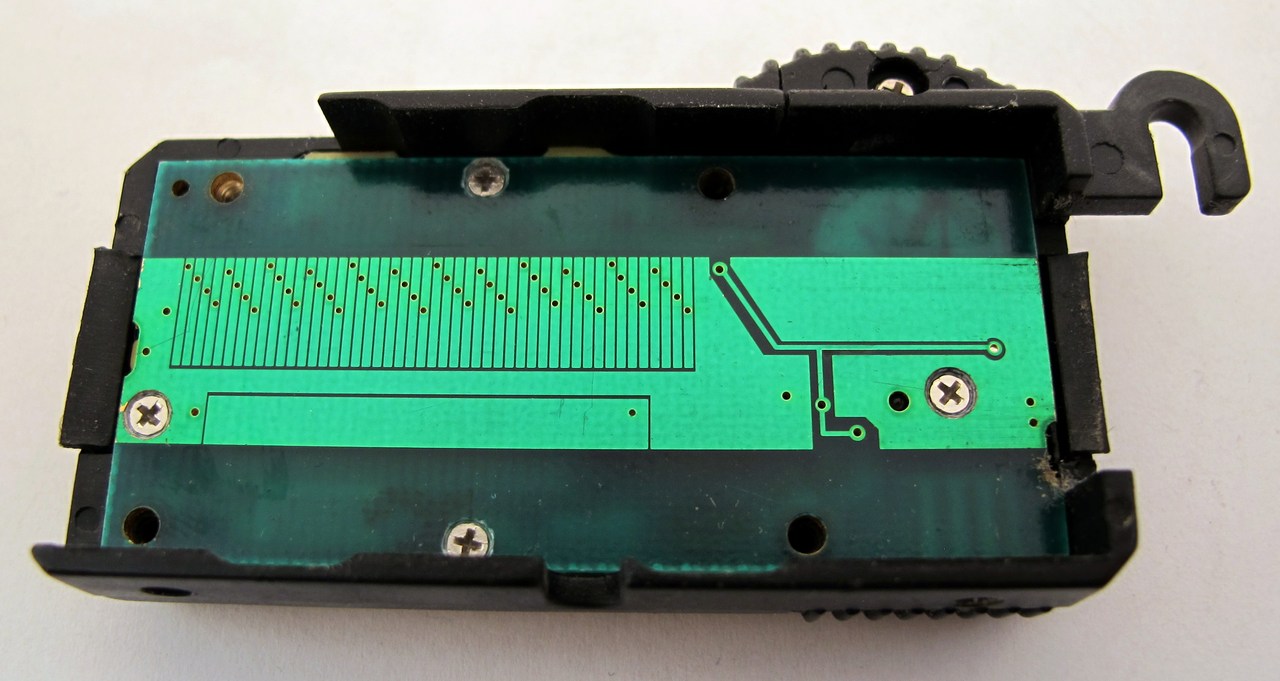
Cover: capacitive linear-sensing electrodes inside a digital caliper slider. Photo: wdwd, CC BY-SA 4.0; resized.

1. Position needs a reference and a direction
“Nine millimetres” is incomplete unless we say where the measurement starts and which direction is positive. A millimetre is one thousandth of a metre. For a sliding carriage, we might define the left end of its path as zero and movement to the right as positive. For a rotating shaft, position is usually an angle relative to a reference direction.
Motion, distance and position answer different questions. A motion detector might tell us only that something moved. A distance sensor can report the separation from a surface. A sensor attached to a carriage can locate it along its travel. With suitable mounting and geometry, a distance sensor can also be used to infer position. The essential question is what the reported number actually describes.
2. What an incremental encoder counts
An encoder converts straight-line or rotating movement into information a device can read. An incremental encoder changes its output as movement occurs. A reader counts those changes, rather like counting ruler marks as they pass a pointer.
A single changing output usually cannot identify direction. Many encoders provide two outputs, A and B, whose changes occur in a different order depending on the direction of motion. The values zero and one describe two distinguishable output states; the permitted voltages depend on the actual encoder and reader.
Readers can count one event per cycle or all four changes across the two outputs. The latter is commonly called ×4 decoding. Consequently, “pulses per revolution” and “reader counts per revolution” are not automatically the same number. Check how the manufacturer defines the quantity and how the reader is configured. TI’s explanation of two-channel outputs illustrates this relationship.
3. A worked example: 40 counts forward, three back
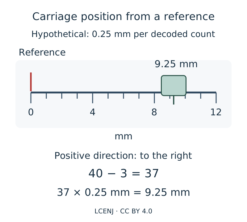
Imagine a carriage that has found its reference and starts at zero. Assume that each final decoded count represents 0.25 mm. This is an invented example, not a specification for a particular product. Taking movement to the right as positive:
| Event | Count relative to reference | Position |
|---|---|---|
| Reference established | 0 | 0 mm |
| 40 counts to the right | 40 | 40 × 0.25 = 10 mm |
| Three counts back to the left | 37 | 37 × 0.25 = 9.25 mm |
The carriage finishes 9.25 mm to the right of the reference. If the reader misses one forward count, the displayed position in this example is 0.25 mm too low. Averaging later position readings does not restore the missing count.
4. Why power loss can require a new reference
In an ordinary counter-based system, the previous count or any movement while power was off may be unknown. Resetting the displayed number to zero does not physically return the carriage to its zero point. The system needs to establish its reference again or use another valid method of retaining position.
The reference might be a mark on a scale or a known location detected by another sensor. Finding that location is often called homing. On a motor-driven machine, homing must follow the machine’s travel limits and safe procedure. Driving into a mechanical end stop is not a universal homing method.
Some rotary encoders provide one index mark per revolution. It identifies a reference within that turn but does not, by itself, identify the total number of turns. An absolute encoder instead provides a distinct code for its distinguishable positions. It still needs correct mounting and a relationship to the machine’s intended zero; “absolute” does not mean that it automatically knows every coordinate of the entire machine.
5. Capacitive describes the sensing method
“Capacitive” describes how movement is sensed. “Incremental” and “absolute” describe how position is represented. These are separate distinctions: depending on its electrode pattern and reading method, a capacitive system can provide incremental or absolute position information.
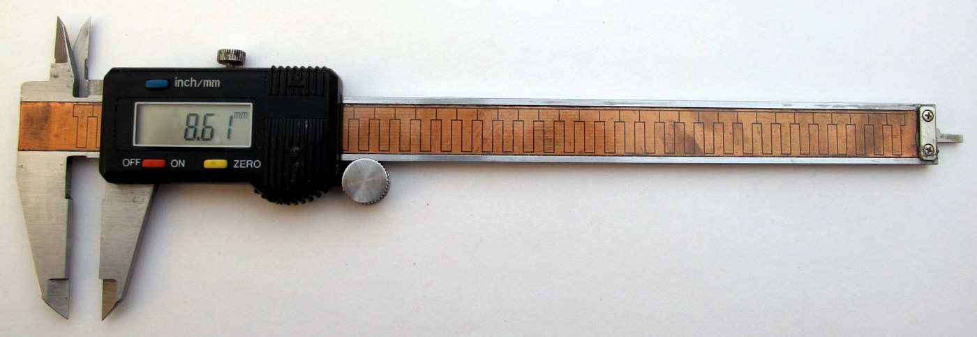
Two nearby metal surfaces separated by an insulating material, such as air, have capacitance. Capacitance relates stored electric charge to the voltage between the surfaces. If voltage and circuits are unfamiliar, the electronics learning path introduces those basics. In a simple arrangement, moving one surface changes their overlap or separation. A reader measures the resulting capacitance change and relates it to position through a known relationship.

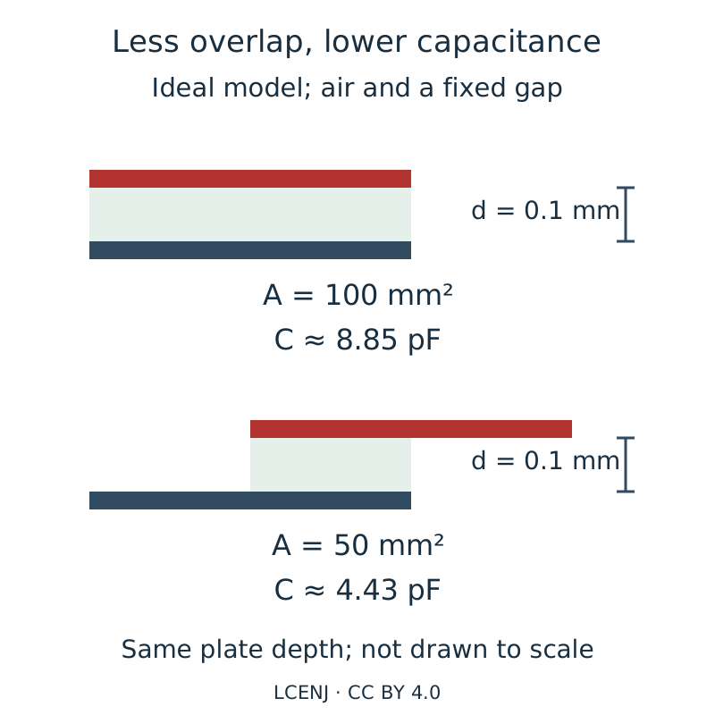
In the ideal parallel-plate model, halving the overlapping area approximately halves the capacitance when the gap and material remain unchanged. As a purely hypothetical calculation, an overlap of 100 mm² across a 0.1 mm air gap gives about 8.85 pF. Reducing the overlap to 50 mm² gives about 4.43 pF. The picofarad, pF, is a unit used for small capacitances. This calculation omits edge effects and wiring capacitance; it is not a finished sensor’s specification.
This is a basic model. Practical sensors can use segmented patterns and more elaborate reading methods; a touch slider, for example, locates a finger from several sensing regions. Humidity, contamination, mechanical spacing and unwanted capacitance in wiring can also change a reading. Contactless sensing still requires attention to mounting and environment. See TI’s capacitive sensing guide and Analog Devices’ sensor and slider design guidance.
6. More displayed digits do not prove accuracy
In the carriage example, the assumed 0.25 mm step describes the position change represented by one count. It does not establish a maximum real-world error of 0.25 mm. Scale errors, a loose coupling, misalignment, missed counts or an incorrect reference can all make the result worse. Displaying two decimal places does not establish measurement accuracy.
To assess a prototype, compare several known positions against a suitable reference. Then approach the same position from both directions and record the differences. This is a proposed check, not a reported hardware result. The lesson on sensor accuracy, resolution and calibration explains these distinctions further.
7. Define the job before choosing a sensor
Start with the motion: linear or rotary, the required travel, and whether returning to a reference after startup is acceptable. Then consider speed, the smallest useful change, allowable error, environment and electrical compatibility. If you only need to know whether an object is present, continuous position measurement may be unnecessary. If position must be available immediately at startup, match that requirement to the documented capabilities of the complete system.
First establish what reference gives the position number meaning. Then check what the sensor and reader actually measure. A capacitive label, a pulse count or extra display digits alone cannot establish the accuracy of the assembled device.
Sources
- TI: Incremental Rotary Encoders — outputs, direction and state counting.
- NI: Using Quadrature Encoders — Encoders and Quadrature Encoders sections. This is an archived document, used here for foundational concepts rather than current board instructions.
- TI: SNOA927A — the parallel-plate model and capacitive measurement limitations.
- Analog Devices: AN-854 — sensor geometry and touch-slider design.
Question and answer article
Ask your technical question
Questions and answers are published after moderation. Authors can see their own pending drafts.
No confirmed questions have been registered for this article yet.