Why Does a 7805 Get Hot? Power Loss and Heatsink Sizing
Calculate 7805 power loss, understand thermal resistance and estimate a heatsink requirement, with a real L7805CV photo and component purchase links.
Contents
A 7805 gets hot because it dissipates the input-to-output voltage difference in proportion to load current. A first estimate is PD ≈ (VIN − 5) × IOUT. Converting 12 V to 5 V at 500 mA produces about 3.5 W of this loss alone. A headline current rating does not establish that the device can supply that load without a heatsink.
Buy the L7805CV: exact part and Iran option
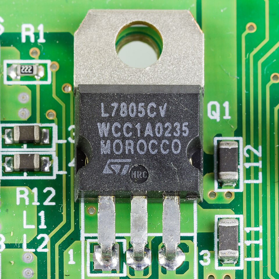
The reference device is STMicroelectronics L7805CV, fixed 5 V, TO-220. The generic name “7805” is insufficient to match the manufacturer, thermal limits and package. Do not assume that a smaller 78L05 or a TO-220FP device is an interchangeable physical part.
| Source | Direct link | Checked on 17 October 2026 |
|---|---|---|
| DigiKey | Buy ST L7805CV, code 497-1443-5-ND | Direct page for the reference device. Check live inventory, packaging and destination-specific shipping when ordering. |
| Iran: ECA | Buy an L7805CV in TO-220 | The product title names the same MPN and package and the page reports stock. The delivered manufacturer's identity and authenticity have not been independently verified. |
| Manufacturer: ST | Official L78 family datasheet | Technical reference for the part and test conditions; not presented as a checkout page or confirmation of direct sales. |
Stock is a dated seller observation, not a delivery or authenticity guarantee. Select a heatsink after calculating loss and mounting conditions; physical size alone is not a thermal specification.

What does a linear regulator do with the voltage difference?
A linear regulator controls the voltage drop across an internal element to maintain its output within the specified regulation range. In a simple model, input current approximately equals load current plus the device's internal consumption. Much of the input-to-output power difference is dissipated in the regulator itself.
A 12 V source is therefore not inherently better than a 9 V source for a 5 V output. At the same current, a larger voltage difference generally increases loss. Reducing input voltage has a limit too: without adequate headroom, regulation is lost. Thermal dissipation and available headroom must be considered together.
Calculate 7805 power dissipation step by step
Start with actual voltage and current under load rather than the adapter label alone. Assuming an exact 5 V output and initially ignoring internal current:
| Input | Load current | Power delivered to load | Approximate regulator loss |
|---|---|---|---|
| 12 V | 100 mA | 0.50 W | 0.70 W |
| 12 V | 500 mA | 2.50 W | 3.50 W |
| 9 V | 500 mA | 2.50 W | 2.00 W |
Load power differs from device dissipation. In the second row, the load receives 2.5 W while the regulator dissipates about 3.5 W. Ideal linear-conversion efficiency is 5/12 ≈ 41.7%.
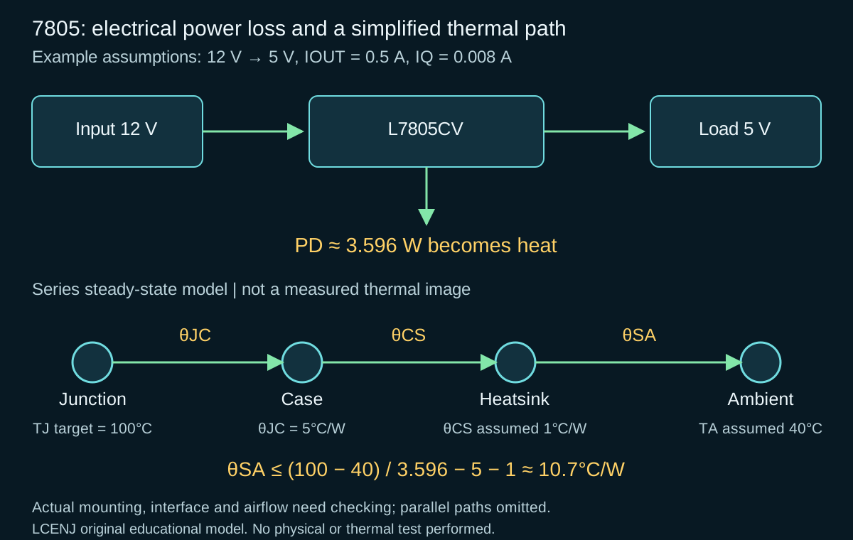
A more complete estimate is PD ≈ (VIN − VOUT) × IOUT + VIN × IQ. If we assume 8 mA internal current for a teaching example, the second row becomes 3.5 + 12 × 0.008 = 3.596 W. That assumption does not replace the device's actual current at its operating temperature and load.
What does thermal resistance mean?
Thermal resistance, expressed in degrees Celsius per watt, approximately relates dissipated power to a temperature rise. θJA describes the junction-to-ambient path; θJC describes junction-to-case behavior. They cannot be substituted for each other.
A simple steady-state estimate is TJ ≈ TA + PD × θJA. Using TA = 25°C and θJA = 50°C/W purely as a model, 0.7 W gives a 35-degree rise. At 3.5 W, the calculation gives 200°C. That result is outside the valid operating range of the device and model: it flags inadequate cooling rather than predicting stable operation at 200°C.
θJA depends on the board, airflow, enclosure and mounting. A datasheet table value is not a measured temperature of your board, and case temperature is not junction temperature. The official TI thermal-dissipation guide explains the thermal paths.
A preliminary heatsink-selection example
Assume the 12-to-5 V, 500 mA conversion has the example's 3.596 W loss and operates in a 40°C enclosure ambient. Set a 100°C junction design target. That target is our choice for this example, not a quotation of the datasheet maximum.
In a simple series model, the path is θJC + θCS + θSA: junction to case, case interface to sink, and sink to air. The ST TO-220 reference gives θJC as 5°C/W. Assume θCS is 1°C/W for this example only.
θSA ≤ (100 − 40)/3.596 − 5 − 1 ≈ 10.7°C/W
This is a starting point for selection. A heatsink specification must apply to the intended orientation and airflow, with additional design margin. An insulating pad, mounting pressure and contact quality can change θCS. The series model does not capture every parallel heat path; final selection needs measurements in the actual enclosure.
Why is the 1.5 A current rating insufficient?
Output-current capability depends on electrical and thermal conditions. Supplying a current during a specified test does not establish the same performance at an arbitrary input voltage, without cooling, inside a sealed box. The voltage difference and the internal element's safe operating range also matter.
Thermal shutdown and current limiting do not replace a cooling design. An output that falls or cycles after a delay can be consistent with protection behavior, but that symptom alone does not establish the cause. Check input voltage, current and temperature. For absolute limits and test conditions, read how to read a datasheet.
Input headroom, dropout and bypass capacitors
The L7805CV is not a very-low-dropout regulator. The ST L7805C table gives about 2 V dropout at 1 A and 25°C junction temperature as a typical value; it is not a fixed guarantee across all loads and temperatures. A 5 V input does not provide the headroom this part needs for a regulated 5 V output.
Ripple and cable drop can reduce minimum input voltage below its nominal value. Conversely, an unloaded source maximum or rail transient can increase loss or stress. Both ends of the input range matter.
The reference test conditions use 0.33 µF input and 0.1 µF output capacitance. Match bypass requirements, capacitor type, connection length and transient load to the application section of the datasheet. A larger capacitor does not eliminate 3.5 W of steady-state dissipation. For pin wiring and the metal tab connection, inspect the exact package drawing in that same datasheet.
When should you consider a buck converter?
With a large voltage difference and substantial current, a switching buck converter can be considered to reduce loss. Heat is not the only criterion: ripple, EMI, transient capability, minimum load, board space and layout also need assessment. A linear regulator may still suit a small current or a noise-sensitive supply.
For a teaching comparison, take a 2.5 W output and assume a hypothetical converter efficiency of 90%. Input power becomes about 2.78 W and total converter loss about 0.28 W. This is neither a measurement nor a performance promise for a market module; check that converter's datasheet and load behavior.
Practical checks and common questions
- Record loaded input and output voltage over time. Do not substitute average consumption for peak current.
- Estimate loss from actual values and measure ambient temperature near the board. State whether the test is in open air or an enclosure.
- Use a controlled load and record the temperature measurement method and settling time. Touch is not a thermometer or an acceptance criterion.
- Recheck intended conditions after changing the input, heatsink or enclosure. The power and brownout troubleshooting guide complements this steady-state analysis for supply transients.
Does a larger heatsink increase efficiency?
In the first-order model, loss from the voltage difference and current remains. A heatsink helps dissipate that heat with a smaller temperature rise.
Can a 7805 directly power an ESP32?
The reference regulator outputs 5 V. The ESP32 chip needs its own appropriate supply rail. A development board with a 5 V input has a separate power circuit that must be checked.
Sources and editorial method
- ST L78 datasheet DS0422 Rev 38: L7805C table, TO-220 thermal data, package and application circuits.
- TI SLVA462: Understanding Thermal Dissipation and Design of a Heatsink.
Sources and purchase links checked on 17 October 2026. Original text and diagram were prepared with AI assistance and reviewed against the references. Numbers are calculations with stated assumptions; this circuit has not been physically or thermally tested.
Question and answer article
Ask your technical question
Questions and answers are published after moderation. Authors can see their own pending drafts.
No confirmed questions have been registered for this article yet.