Relay Flyback Diode: 1N4007 Polarity and Selection
Learn relay flyback diode polarity, coil current paths and 1N4007 selection with a real photo, schematic, energy calculation and component purchase links.
Contents
A relay flyback diode gives coil current a closed path after the driver switches off. For a DC coil with a low-side switch, connect the cathode, identified by the body band, to the positive coil terminal and the anode to the switched terminal. The diode goes across the coil, oriented so that it does not conduct during normal energization.
Buy a 1N4007: exact ordering code and Iran option
The electrical reference here is Vishay's 1N4001–1N4007 family, with 1N4007-E3/54 as a specific ordering example in the axial DO-41 / DO-204AL package. A generic 1N4007 listing does not establish its manufacturer or ordering suffix.
| Source | Direct link | Verification on 16 October 2026 |
|---|---|---|
| DigiKey | Buy Vishay 1N4007-E3/54 | Exact manufacturer part and reference package. Check live inventory, packaging and destination-specific shipping when ordering. |
| Vishay | Official 1N4001–1N4007 product family | Manufacturer specifications and ordering information; this is not a checkout page or confirmation of direct retail sales. |
| Iran: ECA | Through-hole 1N4007 from ECA | The product page reports stock and a minimum order of 50 pieces. Manufacturer and equivalence to the Vishay suffix above are unverified. The example needs one diode, while this seller's minimum order is larger. |
Stock is a dated seller observation, not an authenticity or delivery guarantee. Match the manufacturer, package and relevant datasheet when buying an alternative. No fixed price is quoted.

Why does switching off a relay create a voltage spike?
A coil has both resistance and inductance. Energizing it builds current and a magnetic field. Opening a switch does not instantly remove the stored energy: inductor current cannot jump from its previous value to zero in zero time.
The relationship v = L × di/dt links rapid current change to voltage. Without a suitable continuation path, the switch node rises until an unintended path, such as transistor breakdown or an arc, conducts. A 12 V supply rating alone does not determine the spike amplitude; wiring and stray capacitance also influence it.
The diode does not erase the energy or stop current immediately. It provides a controlled circulation path while current decays. Energy becomes heat in the coil resistance, diode and other losses in that path.
Which way should the band on a 1N4007 face?
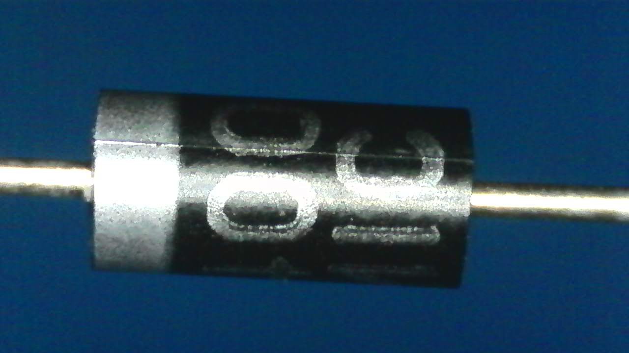
The Vishay datasheet identifies the body band as the cathode. In this DC circuit, the upper coil terminal connects to the positive supply and the lower terminal connects to a low-side switch:
- Cathode K, banded end: positive coil terminal.
- Anode A, unbanded end: lower coil terminal, at the switch node.
- Both diode leads: across the two coil terminals, in parallel rather than series.
Reversing this orientation forward-biases the diode when the switch closes and can create a high-current path through the supply and switch. For a faint band, check the actual device marking and use a diode test with power disconnected rather than relying only on an online photograph.
Follow the current with the switch on and off
Switch on: current flows from the positive rail through the coil and switch to ground. The diode is reverse-biased and is not the main current path.
Switch off: the coil current initially continues in the same direction. The lower coil terminal rises and the diode conducts from anode to cathode. Current now circulates through the coil and diode. This path avoids the need for a very large voltage to sustain that current.
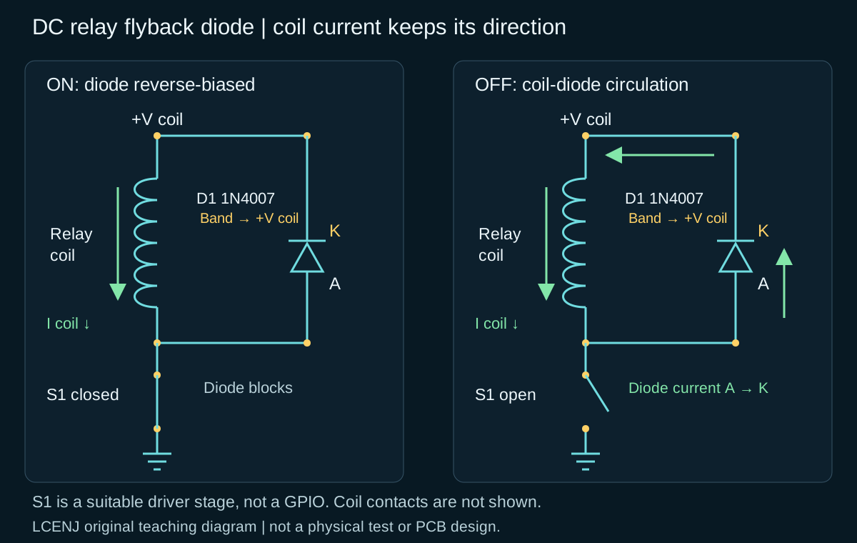
In a simple low-side model, the switch node is clamped near Vrail + VF. This does not mean every node becomes exactly 0.7 V. Forward drop changes with current and temperature, and wiring inductance can still introduce additional overshoot.
Worked example: a 12 V coil carrying 80 mA
Assume negligible switch voltage drop, a steady current of 80 mA and coil inductance of 100 mH. These are teaching assumptions, not verified specifications of a selected commercial relay.
| Quantity | Calculation | Model result |
|---|---|---|
| Coil resistance | R = 12 / 0.08 | 150 Ω |
| Energized power | P = 12 × 0.08 | 0.96 W |
| Magnetic energy before turn-off | E = 0.5 × 0.1 × 0.08² | 0.00032 J = 0.32 mJ |
Immediately after turn-off, diode current starts at approximately the previous 80 mA coil current and then decays. This differs from relay contact current. A relay switching a 5 A contact load does not consequently pass 5 A through the diode across its coil.
The 0.32 mJ energy figure alone cannot predict diode temperature or mechanical contact release time. Switching repetition, current waveform, thermal conditions and mechanical behavior are also needed.
Select the diode using more than its ampere rating
- Reverse voltage: while the coil is energized, the diode sees approximately the supply voltage in reverse. Include the maximum rail voltage and relevant rail transients, then provide appropriate margin; the supply's nominal label is insufficient.
- Current and repetitive pulses: initial current equals coil current at turn-off. Consider average current, repetitive peak current, pulse length and actual temperature together. A non-repetitive IFSM surge rating does not authorize continuous operation at that current.
- Recovery and switching type: the 1N4007 is a general-purpose rectifier. Infrequent relay operation differs from high-frequency motor PWM or a switching converter, where reverse recovery and switching losses need a separate analysis.
- Package and cooling: the Vishay reference specifies 1000 V repetitive reverse voltage for 1N4007 and a 1 A average rating under a 9.5 mm lead-length condition at 75 °C ambient. These figures do not establish unlimited coil energy handling or identical specifications across manufacturers.
For operating conditions, maximum ratings and surge-test conditions, see how to read an electronics datasheet. A seller's headline “1 A” cannot replace those checks.
Why can a diode delay relay release?
Clamping coil voltage to a diode's forward drop allows current to decay more slowly than a higher-voltage clamp would. There can therefore be a tradeoff between switch protection and relay release speed. The official TI inductive-load application brief illustrates the effect with a particular driver and relay; its measured timing must not be transferred to every relay.
A TVS or a diode-and-Zener arrangement may produce faster current decay, but also exposes the switch to a higher voltage. It is not a drop-in replacement without checking switch limits, energy, polarity and relay-maker guidance. A MOSFET's internal body diode also does not automatically provide the correct across-coil path in this low-side circuit.
Wire and check the circuit in steps
- With power disconnected, identify the coil terminals separately from the contacts. This tutorial covers a low-voltage DC coil. COM, NO and NC are not where this diode connects.
- Put the diode close to the coil terminals with a short current loop. Recheck its band and both connections. Some ready-made modules already contain a diode; inspect the module schematic and markings before adding one.
- For initial power-up, use a current-limited low-voltage supply. Do not drive a coil directly from a GPIO or timer output; select a suitable switching stage for the coil.
- Check the rail voltage, coil current and, with an appropriate instrument, the switch node during turn-off. Understand probe-ground connections and input limits. Measurements on the actual circuit complement the calculation.
For a timed control signal, the NE555 one-shot tutorial explains signal generation rather than direct coil drive. For repetitive switching, read PWM frequency and duty cycle.
Frequently asked questions
Can this connection protect an AC coil?
This connection assumes unidirectional DC. A conventional diode across an AC coil can conduct on a half-cycle. Select suppression appropriate to that relay and AC circuit instead.
Does the coil diode also protect the contacts?
It suppresses energy from the coil. Contact arcing when interrupting a separate load is another problem and may require protection matched to that load.
Does the diode eliminate every source of noise?
No. Supply impedance, return paths, wiring and contact loads can still generate interference. A single test without a reset does not prove that every transient is eliminated.
Sources and verification method
- Vishay 1N4001–1N4007 datasheet, document 88503: cathode marking, package and electrical limits.
- TI SLVAF04: inductive-load drive and freewheeling behavior.
Sources and links checked on 16 October 2026. Original text and schematic were prepared with AI assistance and checked against official references. Calculations validate the assumed model only; no coil was built or measured and no finished product was qualified.
Question and answer article
Ask your technical question
Questions and answers are published after moderation. Authors can see their own pending drafts.
No confirmed questions have been registered for this article yet.