PC817 Optocoupler: LED Resistor, CTR and Pull-Up Design
Calculate a PC817 LED resistor, understand CTR test conditions and choose an output pull-up, with a real photo, schematic and verified product links.
Contents
A PC817 optocoupler transfers a signal through light between an infrared LED and a phototransistor. The LED needs a current-limiting resistor, and the transistor output normally needs a pull-up. Select the LED current, CTR grade, output load and timing together. An isolation-voltage rating alone does not qualify a complete interface.
Component purchasing: check the complete ordering code
The numerical reference in this tutorial is Sharp PC817X1NSZ1B, a through-hole DIP-4 device with rank A. The global links below identify that exact ordering code. The regional Iranian listings use the broader PC817 name; an exact match to the reference has not been established.
| Direct product page | Part and package | Observed on October 18, 2026 |
|---|---|---|
| Mouser | PC817X1NSZ1B, DIP-4 | The exact product page showed stock available for shipment. Recheck the current terms before ordering. |
| Digi-Key | PC817X1NSZ1B, 4-DIP | Listed as active and available to order, with lead time; the page says it is not normally held in stock. |
| Iran — ECA | PC817, DIP | Displayed “in stock.” A seller reply mentions rank C, which differs from the rank-A reference. The complete delivered MPN and manufacturer have not been verified. |
| Iran — Atrin Electronics | PC817, DIP-4 | Displayed a quantity of 2 and a Sharp claim in the title. The complete order code and specification consistency are insufficient to establish an exact match. |
These are seller-page observations, not guarantees of stock, authenticity or shipment to a particular country. No fixed price is quoted. The official Sharp datasheet is a technical reference, not a checkout page.
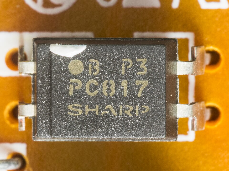

1. Signal transfer with two separate grounds
Current through the input LED produces light that activates the output phototransistor. In the circuit below, the transistor pulls a sensing node toward the output-side ground. The PC817 does not transfer the power supply from one side to the other: both sides need their own appropriate supply and return path.
A typical use is passing a low-voltage status signal into a controller while avoiding a direct ground connection. Joining the input and output grounds elsewhere creates another conductive path and removes galvanic separation of the overall connection. A USB cable or grounded oscilloscope can also create that path unintentionally.
The PC817 is neither an LDR nor an I2C sensor. Its transistor current still needs a suitable reading circuit. See analog and digital sensor outputs for the underlying distinction.
2. Pins, CTR rank and package variants
| Reference pin | Function | Connection in this example |
|---|---|---|
| 1 — Anode | Input LED anode | Positive input current through a resistor |
| 2 — Cathode | Input LED cathode | Input-side return |
| 3 — Emitter | Output transistor emitter | Output-side ground |
| 4 — Collector | Output transistor collector | Pull-up and controller sensing node |
Match these numbers to the package drawing and pin-one mark of the actual device. The table is not a top or bottom physical view. Through-hole DIP, gullwing versions and similarly named parts such as EL817 should not be treated as one ordering code or one datasheet.
The reference's Model Line-up table gives 4–8 mA collector current for rank-A PC817X1NSZ1B under specified test conditions. A generic PC817 purchase does not establish that rank. Use the datasheet-reading guide to distinguish limits, typical curves and their conditions.
3. Calculate the LED resistor for a 5 V example
Start with RIN = (VDRIVE − VF) / IF. Assume a 5 V drive, a 1.2 V LED drop and a 5 mA target: (5 − 1.2) / 0.005 = 760 Ω. Choosing a common 820 Ω resistor gives approximately 4.63 mA and 17.6 mW resistor dissipation at those nominal assumptions.
The 1.2 V value here is an assumption. A typical forward voltage specified at the datasheet's test current does not guarantee the exact drop at 5 mA. As an illustrative tolerance exercise, assume 4.75–5.25 V drive, a 5% resistor and a 1.0–1.4 V LED drop. Combining the extremes gives about 3.89–5.46 mA. That assumed range is not a qualified device limit over temperature.
The driver must supply the current while maintaining an adequate output voltage. A 5 V input-side example is not permission to apply 5 V to an ESP32 GPIO. Check the exact MCU's loaded output voltage and current limits; the 3.3 V and 5 V logic guide covers interface selection.
4. CTR describes a test point, not every operating condition
CTR = IC / IF × 100%. Dividing the reference rank's 4–8 mA output range by its 5 mA test input gives 80–160%. Those conditions also specify VCE = 5 V and TA = 25°C.
Do not extend that range unchanged to arbitrary LED currents, every temperature or an output near zero volts. The 820 Ω input example is not exactly the same test point. Once the transistor saturates, a simple CTR multiplication does not determine the output Low voltage. Typical curves show trends; they are not guaranteed design limits.
Leave room for temperature and long-term changes in optical output and transfer ratio. Increasing LED current without considering power, output load and saturation can create other problems. TI's discussion of CTR variation explains why a single nominal transfer ratio is insufficient.
5. A 3.3 V pull-up produces an active-low signal
Connect the collector to a pull-up powered from the controller side and the emitter to that side's ground. With the LED off, the node rises toward High. With the LED on, the transistor pulls it toward Low. The logic is inverted. The PC817 does not actively drive a High level; omitting the pull-up can leave the input floating.
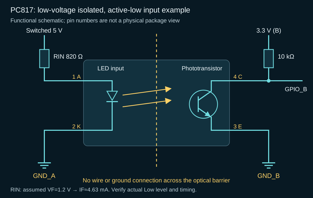
Original educational schematic, not a photograph of a built circuit. Scroll horizontally on a small screen. Pin functions were checked against the reference datasheet. This low-voltage example does not qualify a safety-isolation design.
With 10 kΩ pull-up and an assumed VOL = 0.4 V design target, the transistor must sink about (3.3 − 0.4) / 10000 = 0.29 mA. Check your controller's actual Low-input limit. The reference's VCE(sat) ≤ 0.2 V test uses IF = 20 mA, IC = 1 mA; it does not guarantee that same voltage with the 4.63 mA LED example.
6. Pull-up resistance and speed
A larger pull-up reduces the required sink current but charges output capacitance more slowly. Assuming 30 pF total capacitance and 10 kΩ gives RC = 300 ns. A simple RC model has a roughly 660 ns 10–90% rise time. The capacitance is assumed, not measured, and this calculation is not the complete PC817 delay.
Phototransistor response, load and saturation also matter. Datasheet switching figures use their own load resistance and test conditions. A cutoff frequency or rise-time number does not translate directly into a reliable UART baud rate. A slowly changing switch or alarm status is an appropriate starting application; for fast pulses, select a device with timing specifications suited to the actual interface and check the loaded waveform.
7. Component isolation is only part of board isolation
An input-to-output withstand test is not permission for continuous board operation at that voltage. PCB creepage and clearance, copper underneath the barrier, contamination, connectors and the two supplies all affect the complete system. This tutorial does not design a mains-connected interface.
The collector-emitter voltage rating belongs to the output transistor; it does not make that voltage safe at an MCU input. Likewise, an absolute maximum output current is not the available current at every LED drive. A relay coil usually needs a suitable driver stage. See relay flyback-diode current paths for the separate inductive-load problem.
8. Verify the circuit step by step
- Identify the complete ordering code, rank and pin functions before wiring. A seller's picture does not identify the delivered part.
- Begin with current-limited, low-voltage supplies. Infer LED current from the input-resistor voltage drop and check LED polarity.
- Check the output High with the LED off. Switch the LED slowly and compare the resulting Low voltage with the controller's input limit.
- For the intended rate, connect the actual load, cable and MCU input. Measure edges and turn-on/turn-off delay; an unloaded reading is insufficient.
- Record supply, temperature, rank and results. Check instrument grounds for unintended connections between the two sides.
An output stuck High may indicate reversed LED polarity, insufficient drive or swapped transistor pins. An output stuck Low may indicate continuous LED drive or incorrect wiring at the sensing node. These are proposed diagnostic checks; no physical circuit or timing measurements are reported for this tutorial.
Two practical questions
Can a PC817 convert a 5 V signal to 3.3 V?
An isolated interface can use a 3.3 V output pull-up, provided drive, load, inverted logic and timing are checked. When isolation is unnecessary, a level translator matched to the signal type may be simpler.
Can several outputs share one node?
Open-collector outputs can sometimes pull a shared node Low, but the active input's identity is lost. Analyze leakage, loading and all on/off combinations. Paralleling outputs does not automatically provide a guaranteed increase in speed or usable current.
9. Sources and next steps
- Sharp PC817XxNSZ1B datasheet, OP18002EN: pin functions, Model Line-up and parameter test conditions.
- TI on optocoupler current-transfer-ratio variation: design margins across operating conditions.
- Choosing a digital interface: establish timing needs before selecting the isolating component.
Sources and product pages were checked on October 18, 2026. The original text and schematic are educational. Calculations use the stated assumptions and do not replace verification of the actual circuit.
Question and answer article
Ask your technical question
Questions and answers are published after moderation. Authors can see their own pending drafts.
No confirmed questions have been registered for this article yet.