ESP32 Level Shifting: Connecting 3.3 V and 5 V Signals
Why does the module regulator not guarantee the logic level? Select resistive divider, buffer and I2C bi-directional converter by calculating tolerance and signal type.
Contents
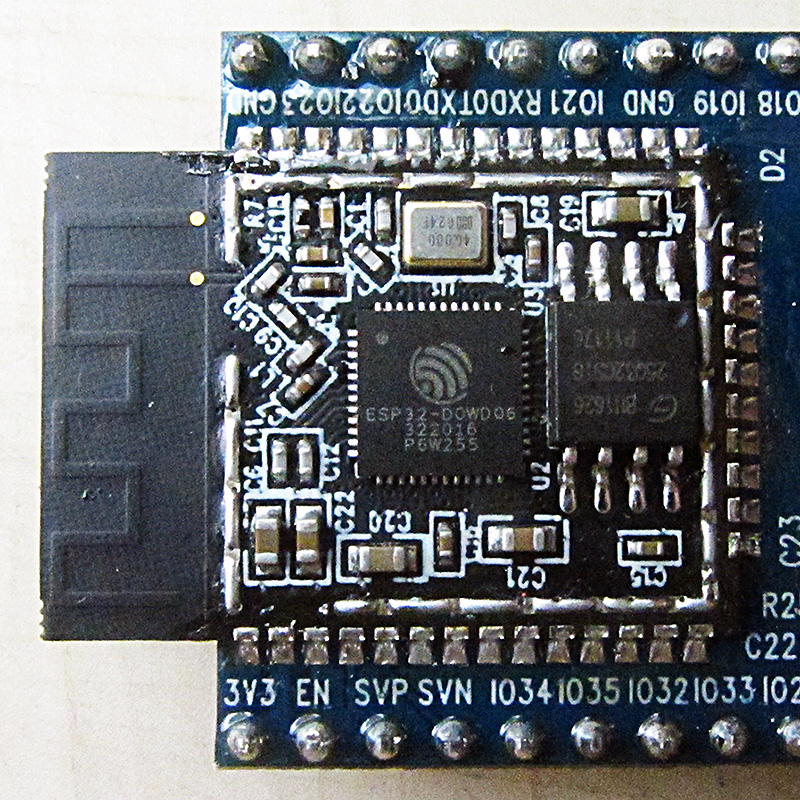

Short answer: first specify the type of signal
Don't connect a 5V output to an ESP32 input just because it has a common ground. First, read the allowed input voltage, High and Low threshold, transfer direction and output type from the documentation of both sides. The regulator on the module may only reduce the power supply to the chip; SDA, SCL, or TX are not necessarily level-converted.
This guide is for low voltage digital signals, not power conversion or connection to the mains. No ready-made resistor or module value is guaranteed without checking the actual circuit, speed, and power supply conditions. If the current connection is unknown, first turn the two boards off and route the wires.
Four numbers that must be read together
| parameter | practical question |
|---|---|
| Input voltage limit | Does it even damage the input in the worst case? |
| VIH(min) | What is the lowest voltage that the High receiver recognizes as valid? |
| VIL(max) | What is the maximum voltage that is considered valid as Low? |
| VOH(min) and VOL(max) | What level does the transmitter actually deliver under specified load? |
To detect compatibility, the minimum High of the sender must be compatible with the minimum High required by the receiver; Low and damage limit should also be checked independently. As you have seen on a sample with a multimeter, 3.3V is not a guaranteed output value under any load and temperature. How to read the condition of the table in How to read the datasheet? It is explained from the absolute limit to the selection of the piece.
Calculation example: reduction of a 5V unidirectional output
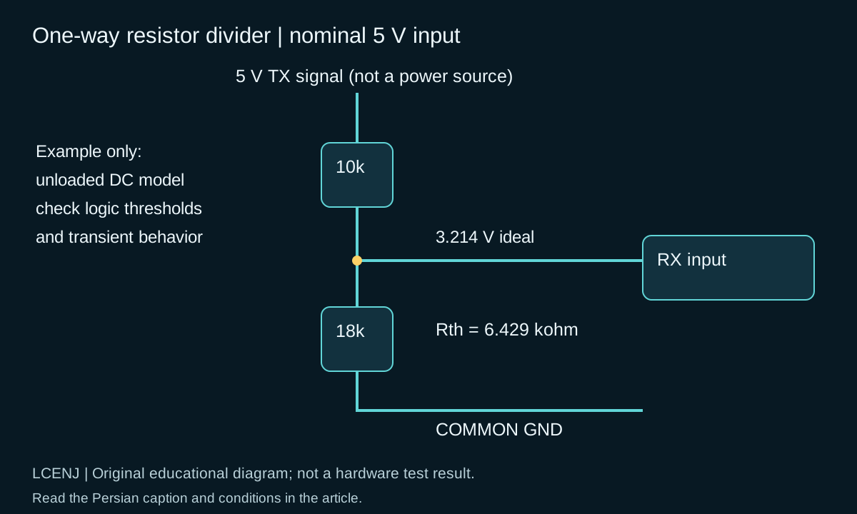
For a unidirectional push-pull signal and high impedance input, resistive divider is one of the options. In the tutorial example, the upper resistance is 10 kΩ from the transmitter to the output node and the lower resistance is 18 kΩ from the node to GND. The input of the receiver is connected to this node; Do not take the receiver's nutrition from this division.
Vout = Vin * Rbottom / (Rtop + Rbottom)
Vin = 5.00 V; Rtop = 10 kohm; Rbottom = 18 kohm
Vout = 3.214 V (ideal, unloaded)
Rth = Rtop || Rbottom = 6.429 kohm
If the assumed ceiling of the transmitter output is 5.25V and the tolerance of both resistors is 1%, the maximum no-load output with Rtop=9.9k and Rbottom=18.18k will be about 3.399V. This is just a calculation; It should be compared with the feed, limit and threshold of the same receiver. Do not include low voltage, leakage current and off state of one of the two boards.
Why is the same division not suitable for every speed and every bass?
The equivalent resistance seen from the node and the input capacitance and the cable form an RC response. If the assumed capacitance is 100 pF, the time constant of this example is about 0.643 µs and the 10-90% rise time is about 1.41 µs. This delay is no longer negligible compared to a UART bit rate of 115200, which is about 8.68 microseconds long.
Decreasing the resistors makes the edge faster, but increases the load and consumption of the transmitter. Check the waveform at the receiver input, not just the transmitter side. For a fast SPI or a long path, do not assume perfect compatibility from a DC calculation of a resistor. Article Difference between I2C, SPI and UART; Choosing the interface for the sensor and module will help you see the protocol limitation.
increase the level of 3.3 to 5 volts; The threshold is decisive
Sometimes the 5V receiver accepts a 3.3 V HIGH level and sometimes it doesn't. This is not clear from the name "5V". For example, the SN74AHCT125 has a VIH limit of 2V at the recommended 4.5-5.5V supply. This part can convert a valid 3.3V signal to a 5V supply-dependent output level.
The buffer example does not permit reverse connection: do not return the buffer's 5V output directly to a non-5V tolerant GPIO. Enable base, unused inputs, load current and turn on sequence should be designed according to the datasheet. Don't put a one-way buffer instead of a two-way converter on the common bus.
I2C requires round trip and pull-up
In conventional I2C, both sides can pull the line Low, and pull-up resistors make the line High. A simple resistive divider does not maintain the same behavior. An example of a specific part for this application is PCA9306; The setting of the reference and enable bases and the resistors on both sides should be read from the proposed circuit of the same part.
The presence of four channels on a generic module does not mean absolute compatibility with any speed, SPI or UART. Multi-board pull-ups can be paralleled. Use the TI manual to calculate bus resistance and capacitance, and I2C Troubleshooting in ESP32 to find the cause of the unresponsiveness.
Acceptance test and common questions
Fill out the accompanying sheet for each line separately: name of transmitter and receiver, direction, voltage range, rate, estimated capacity and power failure mode. Then start with a short circuit and a device; Measure the free and active area and increase the number of devices only after confirmation.
Are all STM32 GPIOs 5V tolerant?
no Read the tolerance mark, base type and feeding conditions of the same model from the datasheet; Especially don't assume an analog input like a digital GPIO.
Is series resistance only level conversion?
No by itself. Relying on an internal protection diode and limiting the current is not a common method of surface conversion without the express permission of the specification.
If both boards are 3.3V, no further investigation is necessary?
Leakage, ground difference, lighting order and output type are still important; The voltage name does not guarantee the soundness of the wiring.
Official sources and accompanying files
Technical resources were reviewed on 10/13/2026. Match the version and model of your part with the related document.
Get the decision sheet and test registration (CSV); The full package of the article and accompanying files are available from the download section of this page.
Compilation method: preparation and technical review with the help of artificial intelligence tools, official sources and computational examples. Hypothetical numbers are labeled as examples; Compilation or software testing does not replace real part and circuit testing.
Question and answer article
Ask your technical question
Questions and answers are published after moderation. Authors can see their own pending drafts.
No confirmed questions have been registered for this article yet.