ESP32 Resets: Brownout and Power Supply Troubleshooting
Reset when Wi-Fi, turn on the load or check the USB connection step by step; Isolate cable drop, source capacitance, regulator, EN and capacitor placement from software error.
Contents

Short answer: Keep the Reset report
An ESP32 reset when Wi-Fi is turned on or the load state changes can be related to a power drop, but not every reset is a Brownout. First, record the serial output of the startup time, firmware version, load conditions and reset reason. Then test the hypothesis by changing one factor. Removing the error message or turning off the brownout detector is not a power supply modification.
This article is about ESP32 classic and low voltage lab circuit. Design values should be adapted to your exact module and board. No waveforms or physical test results from the LCENJ lab are provided in this manual.
Three signs that do not have the same cause
| sign | Testable hypothesis | Separator test |
|---|---|---|
| Reset simultaneously with radio transmission | Consumption jump and rail drop | Record the 3.3V rail close to the module with the same load |
| Reset at almost constant time interval | Watchdog, blocked path or application error | Reset report and task scheduling |
| Reset by touching the cable or moving the board | Poor connection, EN or connector | Mechanical investigation and continuity in de-energized state |
| Crash after adding load | Common ground path or source load | Temporarily disconnecting the load and repeating the same scenario |
Simultaneity is primary evidence and does not prove causation by itself. For example, network activation can both change consumption and execute a new path of code. Reporting and measurement should separate these two possibilities.
From the USB to the power base, you have a chain
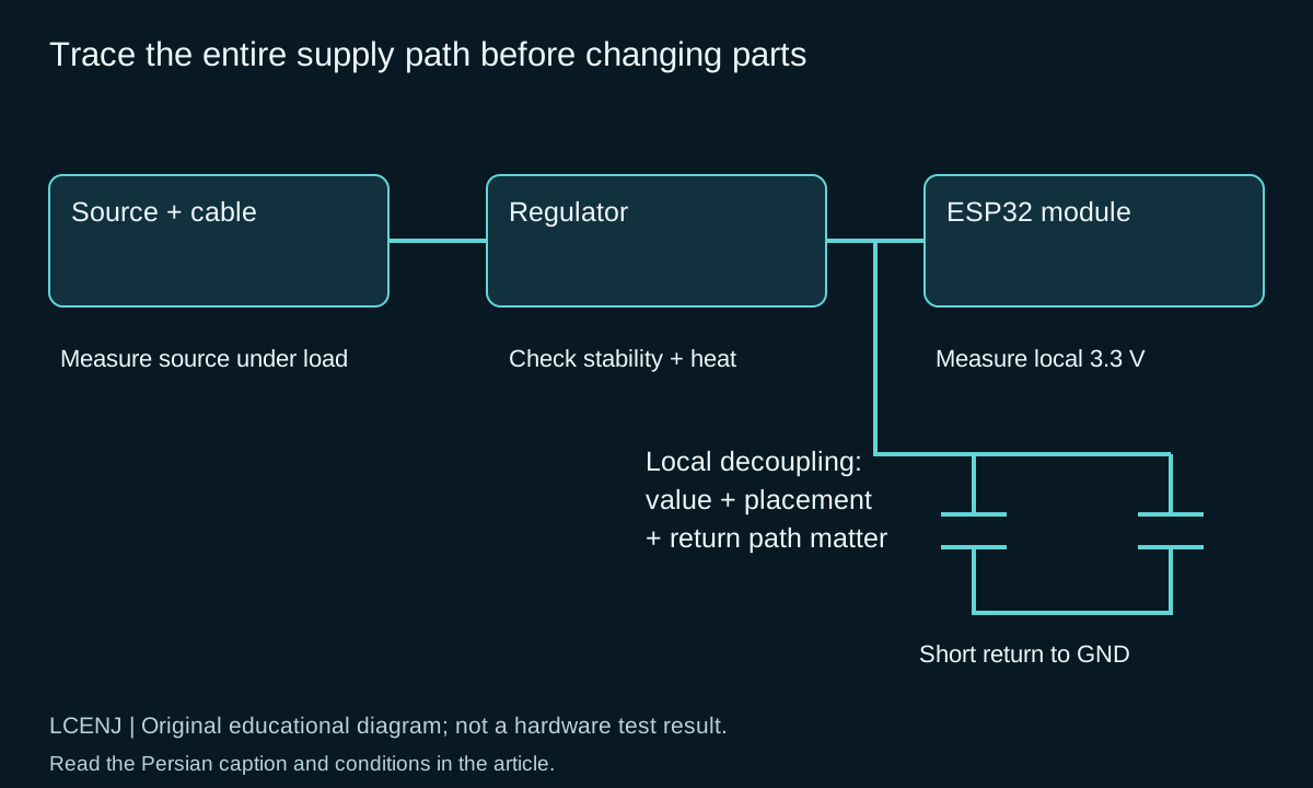
Draw the actual route on paper: source, cable, connector, protection, regulator, PCB route and module. A good voltage at the source does not guarantee a good voltage at the module. In a purely hypothetical example, a 0.8 ohm path-to-return resistance and a 0.3 amp current increase would create an additional 0.24 volt drop.
DeltaV_path = DeltaI * Rpath
DeltaI = 0.30 A; Rpath = 0.80 ohm
DeltaV_path = 0.24 V
The number on the adapter also does not show its transient response. For comparison, use a short, healthy cable and a properly tuned source and measure the rail under the same firmware scenario. Do not judge the quality of a cable from the thickness of its coating.
What does a bypass capacitor do?
The capacitor near the consumer can provide part of the transient current in the short path. Capacitance, ESR, ESL and ground return path contribute to the result. A few capacitors away from the module does not necessarily equate to a good capacitor in the right place. The ESP32 Schematic guide recommends 3.3V with a supply capacity of at least 500 mA and an input capacitor of at least 10 µF for a single power supply; This number is not the permanent consumption of your board.
To show the scale, if the ideal capacitor alone delivers 100 mA for 1 ms with a 0.1 V drop, C = I x dt/dV equals 1000 µF. This calculation does not recommend installing such a capacitor: in a real circuit, the regulator also flows, and a large capacitor can cause inrush current and stability issues.
Don't forget the regulator and ground path
In an LDO, the difference between input and output voltage is converted into heat. The hypothetical example of converting 5 to 3.3 V at an average current of 200 mA has losses of about 0.34 W. We do not find the bond temperature from this number alone; Package, copper PCB, variable current and environmental conditions are also required.
Do not pass the current of the motor, relay or LED load through the same narrow return path of the sensor and module. The power path and signal reference must be consciously designed; Arbitrarily cutting off the earth's surface is not a general solution either. For placement, match the builder's PCB guidelines to the actual board. For load control, What Is PWM? Arduino Frequency and Duty Cycle Examples and MOSFET article of the site are useful.
A phased test instead of randomly swapping parts
- Keep firmware and boot log constant; Record the time and type of reset.
- Disconnect the external loads and repeat the same network scenario.
- With the power off, check the connector, ground and EN connection.
- Change the cable and then the source separately; Only one change at a time.
- Check the rail near the module and compare with the allowed range of the module.
- After correction, repeat cold start, network reconnect and load change.
The multimeter may not show a very short drop. If you are using a desktop oscilloscope, know the ground connection of the instrument and work only on a suitable, isolated low-voltage circuit; Do not connect the ground clamp to an unknown point or city electricity. The goal is to observe the rail at the place of consumption; The long probe wire itself can spoil the measurement.
Common questions and end criteria for troubleshooting
Is a 100 nanofarad capacitor enough?
No for all mutations. The amount and placement of local capacitor, bulk capacitance and source must be a consistent set.
Does turning off Brownout solve the problem?
The voltage drop remains and you may hide the invalid behavior. First, correct the cause of power supply and startup conditions.
Does USB operation validate the battery design?
no The power path and the transient response of the two modes are different; Both should be tested in their working situations.
Write the end of the troubleshooting with a criterion: for how long, how many connections and what load changes, without reset and with allowed rails. The registration form with the article is for this purpose. To detect blocked waiting in the code, Arduino programming without delay; Read millis and multitasking.
Official sources and accompanying files
Technical resources were reviewed on 10/13/2026. Match the version and model of your part with the related document.
Get the decision sheet and test registration (CSV); The full package of the article and accompanying files are available from the download section of this page.
Compilation method: preparation and technical review with the help of artificial intelligence tools, official sources and computational examples. Hypothetical numbers are labeled as examples; Compilation or software testing does not replace real part and circuit testing.
Question and answer article
Ask your technical question
Questions and answers are published after moderation. Authors can see their own pending drafts.
No confirmed questions have been registered for this article yet.