What Is PWM? Arduino Frequency and Duty Cycle Examples
PWM is not a constant analog voltage; Learn frequency and brightness ratio separately with ideal wave, LED lighting example, RC filter calculation and Uno compilable code.
Contents
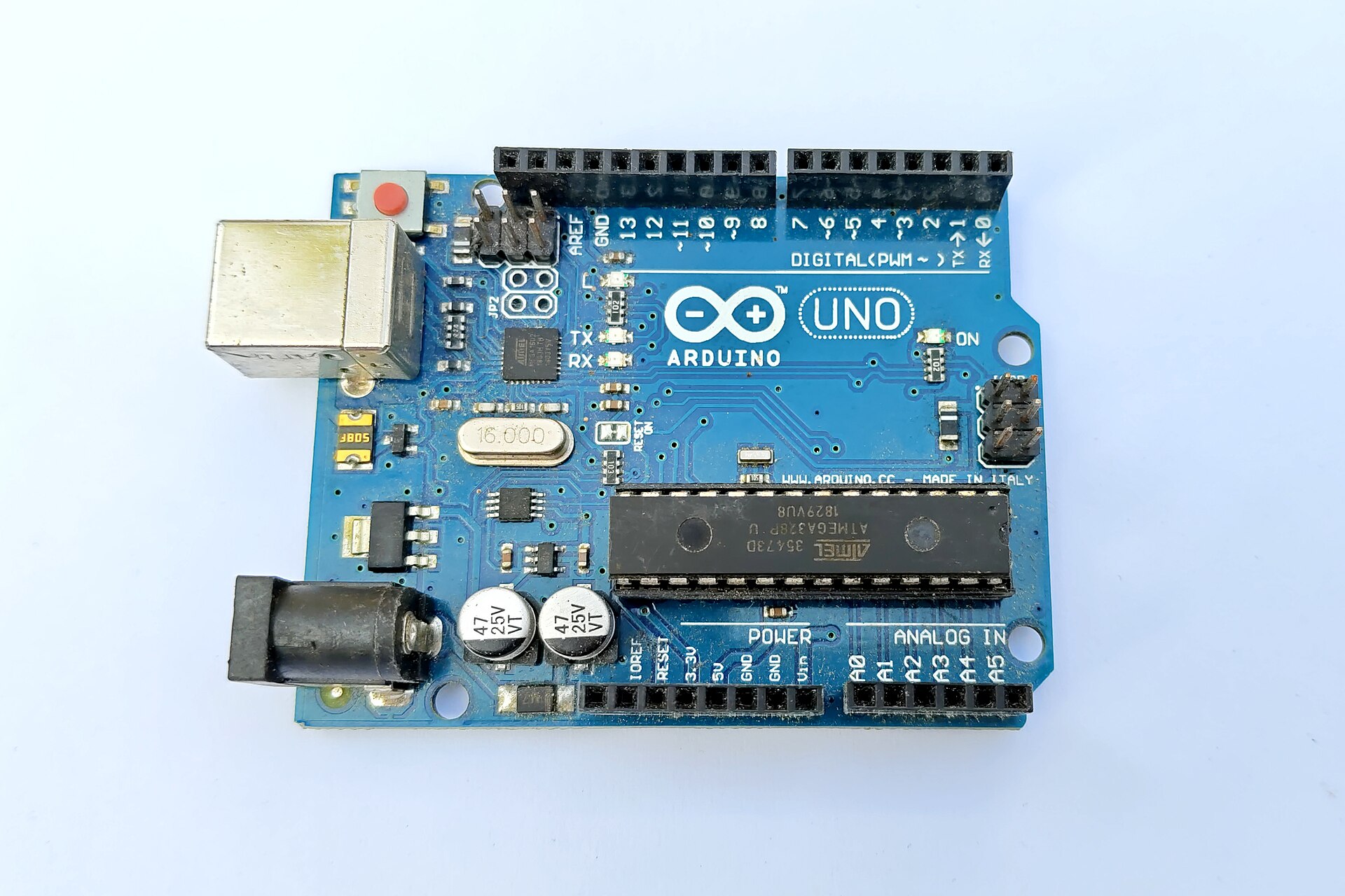

Short answer: we control the time it is on
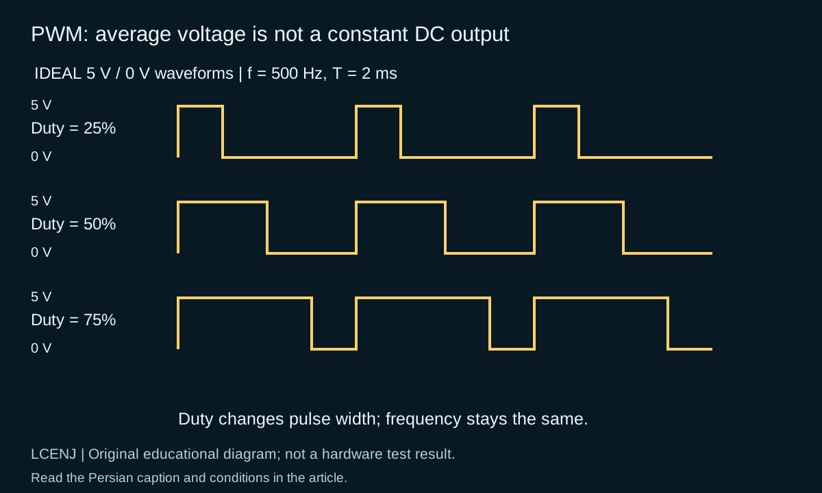
PWM is a pulsed output whose high time portion changes. Frequency tells how many cycles we have per second and Duty Cycle tells what proportion is on in each cycle. Changing one does not necessarily change the other. In the 5V output with Duty equal to 50%, the signal goes between Low and High; The output is not constant 2.5V all the time.
The example code in this article is for the Arduino Uno R3. Do not generalize the behavior of timer and PWM base to Uno R4, ESP32 or STM32. The accompanying graph is an ideal mathematical waveform and not an oscilloscope picture or actual board test result.
Calculate period, frequency and duty
| quantity | relationship | Educational example |
|---|---|---|
| T period | One cycle time | 2 ms |
| frequency f | 1/T | 500 Hz |
| High time | D × T | For D=25% equal to 0.5 ms |
| The ideal average | D×Vhigh + (1−D)×Vlow | With High=5V and Low=0, at 25% equals 1.25V |
Average does not explain all load behavior. Motor, resistor, LED and digital input do not respond the same to the same pulse. The actual range of the GPIO is also not assumed to be equal to the power rail under load; Check the allowable current of base and driver separately.
Uno example: five timed lighting commands
For low current test, connect a common LED with a 1 kΩ series resistor from D9 to the LED anode and cathode to GND; Disconnect power before wiring. Do not connect high power LED, LED strip or motor to GPIO. For them, a suitable driver and a separately designed source are required.
The program gives the next command every two seconds: zero, 64, 128, 192 and 255. For the Uno R3, the default analogWrite API uses the range 0 to 255. Pin 9 is around 490 Hz in the default setting of the AVR core; The 500 Hz waveform is just to simplify the calculation. The reference analogWrite details the boards separately.
#include <Arduino.h>
#if !defined(ARDUINO_AVR_UNO)
#error "This example is qualified for Arduino Uno R3 only."
#endif
constexpr uint8_t PWM_PIN = 9;
constexpr uint8_t LEVELS[] = {0, 64, 128, 192, 255};
uint8_t nextLevel = 0;
uint32_t lastChange = 0;
void setup() {
  pinMode(PWM_PIN, OUTPUT);
  analogWrite(PWM_PIN, 0);
  Serial.begin(115200);
  lastChange = millis();
}
void loop() {
  const uint32_t now = millis();
  if (uint32_t(now - lastChange) < 2000UL) return;
  lastChange = now;
  const uint8_t value = LEVELS[nextLevel];
  analogWrite(PWM_PIN, value);
  Serial.print(F("PWM command (0..255): "));
  Serial.println(value);
  nextLevel = (nextLevel + 1) % (sizeof(LEVELS) / sizeof(LEVELS[0]));
}
The printed number is the "PWM command", not the measured brightness. The human eye does not have a linear response; Doubling the steering is not necessarily doubling the perceived brightness. The code is compiled for the Uno R3; Physical LED test is not done.
Higher frequency is not always better
Low frequency may cause flickering or audible noise; Higher frequency also increases the number of switching, losses and driver requirements. In many timers, the number of counts per cycle is split between frequency and duty cycle. Read the exact limit from the timer of the same MCU.
On the Uno, changing the timer setting can interfere with timing libraries or functions. The code above does not reset the timer. If you are using a motor or an inductive load, energy containment and gate behavior belong to the power section; Article NMOS and PMOS and ESP32 Resets: Brownout and Power Supply Troubleshooting See also
Does the output become smoother with the RC filter?
For an impedance input, a low-pass filter can reduce the fast PWM component, but the output still has ripple and settling time. An ideal example of R=1 kΩ and C=10 µF gives a time constant of 10 ms and a cutoff frequency of about 15.9 Hz. Five time constants are approximately 50 ms; This number is ideal for the step response of the model without additional load.
tau = R * C
fc = 1 / (2 * pi * R * C)
R = 1000 ohm; C = 10e-6 F
tau = 0.010 s; fc = 15.915 Hz
If the load has low resistance, both the final level and the response will change. A small RC is not a load power source. Compare ripple, tolerance, buffering and DAC requirements for accurate analog output. The accompanying calculation file shows the average difference and model ripple.
Common errors in measurement and use
| wrong | correction |
|---|---|
| The multimeter shows 2.5 V, so the DC output is stable | Check waveform, instrument measurement mode and frequency |
| Give PWM to each pin | Select the supported base and timer of the same board |
| To double the power, double the duty | Consider load type, voltage and driver losses |
| Zero command means the power circuit must be off | Test Reset, Pull-down and Driver mode independently |
For checking, record command, observed duty, frequency, current and driver temperature separately. Do not make a thermal confirmation of a product from a part not heating up in a few seconds.
Common questions
Is analogWrite the same as DAC?
On the Uno R3 in this example, the output is PWM. Some boards have a DAC base; Do not interpret the function name without the board specification.
Does LED have linear lighting with steering wheel?
Perceived brightness is not necessarily linear and the actual current depends on the LED circuit. The command number is not a unit of lux or lumen.
What frequency should we choose for the motor?
Start with engine, driver, sound, loss and test specifications; There is no general number for all engines.
To execute multiple tasks simultaneously without a two-second pause, structure the program in Arduino programming without delay; Read millis and multitasking.
Official sources and accompanying files
Technical resources were reviewed on 10/13/2026. Match the version and model of your part with the related document.
Get the decision sheet and test registration (CSV); The full package of the article and accompanying files are available from the download section of this page.
Compilation method: preparation and technical review with the help of artificial intelligence tools, official sources and computational examples. Hypothetical numbers are labeled as examples; Compilation or software testing does not replace real part and circuit testing.
Question and answer article
Ask your technical question
Questions and answers are published after moderation. Authors can see their own pending drafts.
No confirmed questions have been registered for this article yet.