I2C vs SPI vs UART: Choosing a Sensor Interface
From the number of wires and clock to the data format and voltage level; Compare the three common interfaces with the example of sensor, display and serial module and find the error step by step.
Contents

Short answer: Select the interface from the device type
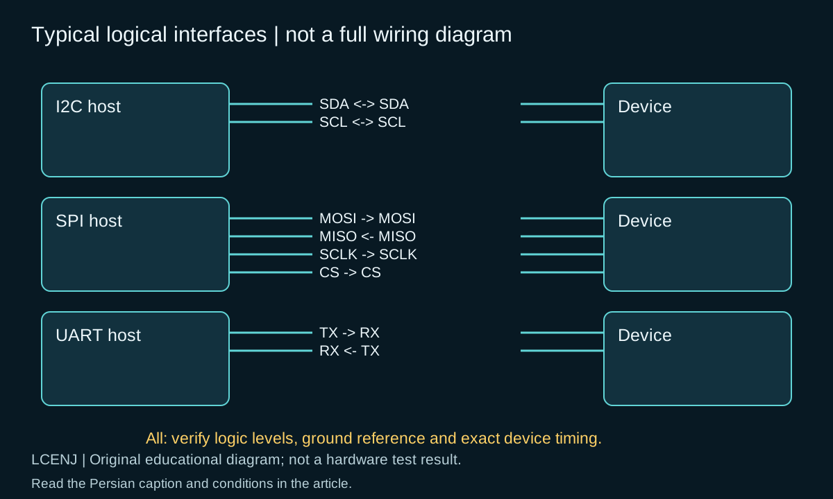
I2C is used for multiple compatible components on two shared lines, SPI for simultaneous exchange with clock and device selection, and UART for serial transmission without a shared clock line. No one is a winner of all projects. First, determine what interface the part has, what rate and delay you need, and what voltage level is allowed.
This comparison is about short-circuited logic interfaces. Do not confuse logic level UART with RS-232 or RS-485; They need the appropriate electrical layer and driver. Increasing Baud or Clock also does not correct improper wiring and level difference.
Table of differences in conventional modes
| Feature | I2C | Common four-wire SPI | Common UART |
|---|---|---|---|
| Main signals, except ground | SDA and SCL | SCLK, MOSI, MISO and CS | TX and RX |
| Shared clock | has | has | does not have; The setting of both sides should be compatible |
| Choose recipient | Bus address | Usually separate CS for each device | Usually a link; address if needed in higher protocol |
| line behavior | Open-drain and Pull-up in conventional mode | dependent on device specifications; Normally active output | depending on the output and logic level of the device |
| Startup tip | Address, Pull-up and capacity | Mode, bit order and CS | Baud, frame format, level and TX/RX intersection |
There are three-wire, semi-double-wire and special modes; The table is the description of conventional modes. Fewer wires does not always mean less cost or trouble. See the limit of the number of bases and the number of devices in addition to the speed and length of the route.
I2C: The right address is just the beginning
In a temperature and light project, the SHT31 and BH1750 can be placed on a common bus if they are electrically and address compatible. But the ACK response in the scanner does not prove the model of the part or the validity of the data. Command, response length, conversion time and document data validation are still required.
Don't confuse the 7-bit address format with the number containing read/write bits. Multi-module pull-ups may be paralleled and the cable capacity will change the pull-up time. Follow this issue in I2C Specifications and I2C Troubleshooting. For 5 and 3.3V level, connect 5V to ESP32; The selection of 3.3 and 5 V level conversion complements this section.
SPI: Setting Mode and CS is part of the contract
In SPI, sending a few bytes with the correct clock is not enough. CPOL specifies the idle level of the clock and CPHA specifies the sampling edge. Read Mode, bit order, maximum Clock and times before and after CS from the datasheet of the same display, memory or sensor. Don't generalize one instrument setting to all parts on the bass.
If they share multiple MISO devices, they should release the line in deselected state by design. Two active outputs on the same line can be interlocked. To setup, just plug in a device, start with a low allowed clock, and get a short transaction with a specified response. Check the CS logic in the actual Capture, not just in the function name of the code.
UART: No shared clock line, contract still required
The TX of one side goes to the RX of the other side and its RX goes to the opposite TX; Ground reference and logic level must be appropriate. Both parties should set Baud, number of data bits, Parity and Stop according to the contract. For example, setting 115200 and 8N1 does not mean a complete protocol for product commands.
If we have a Start, eight data bits and a Stop in each frame, each data byte takes ten bits on the line. The theoretical ceiling of data at 115200 is about 11520 bytes; It reduces the frame interval and protocol overhead. This number is not a test result of a module or a guarantee of message delivery. For binary data, explicitly design the length, message boundary, error status, and timeout.
From nominal rate to useful data; A selection example
Let's say you want twelve bytes of valid data per 100 ms; The useful requirement is only 120 bytes. In this project, sensor conversion time, data validity, and error handling are probably more important than maximum interface speed. Conversely, for a large-frame display, count the number of bytes and refresh rate, and then measure bandwidth and MCU resources.
Fill in five boxes for each option: connected devices, useful data rate, path length, voltage level, and disconnection behavior of one of the devices. If you have a long path or a noisy environment, check the choice of transceiver and physical layer; Do not convert the short SPI or I2C of the board to an industrial cable without a witness.
Troubleshooting order and common questions
- Identify the model and actual bases of the two sides.
- With the power off, check the wire path and ground; Then measure the feed and the level of the lines.
- Choose a device and a small transaction with specific settings.
- Record the raw data, length, time and error status next to the result.
- After the connection is correct, increase the number of devices or the speed step by step.
Is SPI always faster than I2C?
In many applications it is capable of higher speeds, but the actual limit is determined by the device, MCU, and path design; The interface name number is not enough.
Is UART always two-way communication?
It can be bidirectional, but the wiring and application may only use one direction. Check the contract and resources of the same device.
Which is easier for multiple sensors?
I2C can reduce the number of lines if the address, level and capacity are compatible; For SPI devices, note the shared line selection and release.
To continue, ESP32 vs STM32: Choosing a Microcontroller for Your Project and How to read a datasheet? Read From Absolute Limit to Part Selection and fill out the selection sheet attached to this article for your own project.
Official sources and accompanying files
Technical resources were reviewed on 10/13/2026. Match the version and model of your part with the related document.
Get the decision sheet and test registration (CSV); The full package of the article and accompanying files are available from the download section of this page.
Compilation method: preparation and technical review with the help of artificial intelligence tools, official sources and computational examples. Hypothetical numbers are labeled as examples; Compilation or software testing does not replace real part and circuit testing.
Question and answer article
Ask your technical question
Questions and answers are published after moderation. Authors can see their own pending drafts.
No confirmed questions have been registered for this article yet.