From pressure to numbers: inside SparkFun’s Qwiic MicroPressure
Follow pressure from the sensor port to I²C data: power, pull-ups, PCB routing, unit conversion and specific reading limitations in the pinned library.
Contents
Qwiic MicroPressure turns pressure applied at its sensor port into digital data. A host microcontroller reads that data and converts it into units such as kilopascals. The central architectural choice is a sensor that handles conversion and compensation internally. Power quality, tubing, valid communication and fault handling still belong to the surrounding system.
Imagine an instrument displaying pressure in a low-pressure air chamber. Before wiring anything, ask “relative to what?” The reviewed model measures absolute pressure, relative to its internal vacuum reference. An open port in ordinary air should therefore not read zero. Measuring pressure relative to the surroundings requires an ambient reference or a sensor suited to that measurement.
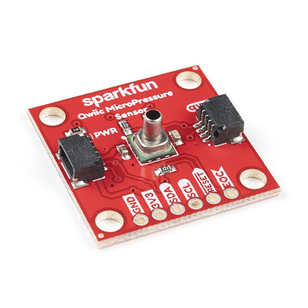
Choosing the board and sensor
The assembled board is SEN-16476. Its Honeywell MPRLS0025PA00001A sensor has an approximately 5 × 5 mm surface-mount body, a long port, an I²C interface and a 0–25 psi absolute range. Psi is a pressure unit; 25 psi is about 172.4 kPa. The assembled breakout, the bare sensor and other MPR variants are different purchasing and integration choices.
To use this project’s circuit, select the SparkFun SEN-16476. For another module, compare the sensor type, pressure range, supply and pinout with this revision.
Which revisions are being examined?
The hardware belongs to SparkFun/MicroPressure_Sensor at 8dbe741d…, committed on 20 July 2020. Its schematic and PCB are Eagle files. Software is examined separately at MicroPressure Arduino Library commit a8b0e0c0…, dated 29 August 2021, library version 1.0.1. Those are two repository revisions, not a shared firmware-and-hardware release.
Manufacturer requirements were checked against the current MPR datasheet, document 32332628, Issue K, retrieved today. It is distinguished from the older PDF bundled in the hardware repository. The circuit files support the analysis; repository age or popularity does not establish engineering quality.
From the port to the digital interface
Inside the sensor, a piezoresistive structure converts pressure into an electrical change. Internal electronics process it and prepare digital output. There is consequently no external instrumentation amplifier or separate ADC on this breakout. Integration removes components from the board, but does not choose the pressure reference or validate a received sample for the host. Unlike OpenScale with its HX711, the sensing bridge is not routed into an external converter on this board.
U1 is the sensor. C1 is a 0.1 µF supply-to-ground capacitor. C2 is 1 nF between VO+ and VO−, sensor pads 4 and 6; it is not the supply bypass capacitor. The symbol also names SPI-related signals. Those names do not mean that this I²C order code can become an SPI sensor through a software change.
| Actual connection | Function on this board |
|---|---|
| U1 pads 12 and 10 | Supply and ground; the 3.3V net reaches U1 directly |
| U1 pads 2 and 3 | SDA and SCL, shared by both Qwiic connectors and J3 |
| U1 pads 9 and 8 | Active-low reset and end-of-conversion, exposed on J4 |
| R1 and R2, 2.2 kΩ each | SDA/SCL pull-ups through the I2C jumper |
| R4, 2.2 kΩ | Holds reset high during ordinary operation |
| PWR, R3 at 1 kΩ and D1 | Power-indicator branch; its jumper is separate from the pull-up jumper |
Power and pull-ups shape the system
The schematic's 3.3V net does not pass through an onboard regulator. The parsed component list contains no added input-protection device or logic-level translator. The sensor's specified supply range is 1.8–3.6 V; that does not make this board's input 5 V tolerant. A straightforward integration uses a 3.3 V host and bus with a shared ground. Obtain host I²C pin numbers from that host's documentation, rather than relying on wire colours.
I²C is a communication bus using an SDA data line and an SCL clock line. Devices can share these lines when addressing and electrical requirements are handled correctly. Pull-up resistors raise a line; a transmitting device pulls it low to send zero. Assuming approximately zero volts in the low state, one 2.2 kΩ resistor draws 1.5 mA from 3.3 V. Four boards with identical enabled pull-ups produce an effective 550 Ω and approximately 6 mA per low line. This arithmetic motivates checking the entire bus. It neither proves that four boards fail nor grants permission to sink that current through any pin.
I ≈ 3.3 V / 2200 Ω = 1.5 mA
Rparallel = 2200 Ω / 4 = 550 Ω
Iparallel ≈ 3.3 V / 550 Ω = 6 mA
Increasing resistance also slows the rising edge. With an explicitly assumed total bus capacitance of 100 pF, the I²C guide’s RC estimate for the 30–70% rise time is approximately 186 ns: tr ≈ 0.8473 × R × C. Cable and input capacitance were not measured, so this does not qualify an arbitrary cable. Check effective pull-up resistance, low-level voltage and edge timing on the assembled bus, then disconnect only surplus pull-ups using the appropriate jumper.
For the indicator, assuming a 2 V LED drop gives approximately 1.3 mA through R3. This is a design estimate, not measured current. It explains why the indicator branch deserves attention in a battery-powered instrument. Cutting PWR disconnects that LED branch; it is not a sensor power switch, and it does not prove a particular reduction in total measured consumption.
A proposed 4.7 kΩ replacement for R1/R2, under that same assumed 100 pF load, would reduce each line's current to approximately 0.7 mA but increase rise time to about 398 ns, beyond Fast-mode's 300 ns limit. “Use larger resistors to save power” is therefore incomplete without a timing budget. Replacing U1 with another pressure model also requires matching reference type, pins, interface, range and conversion endpoints. Sharing the MPR family name does not establish complete compatibility.
What the PCB reveals about assembly and noise
U1 is near the centre of the 25.4 × 25.4 mm board. C1 and C2 sit on opposite sides of it. Side-mounted Qwiic connectors support chaining, while lower headers expose the main signals and reset/EOC. The listed resistors and capacitors use 0603 packages; matching a replacement's value alone does not establish mechanical or electrical suitability. Allocate space for the port and tubing early. Tube-fitting forces should not be carried through the sensor's solder joints.
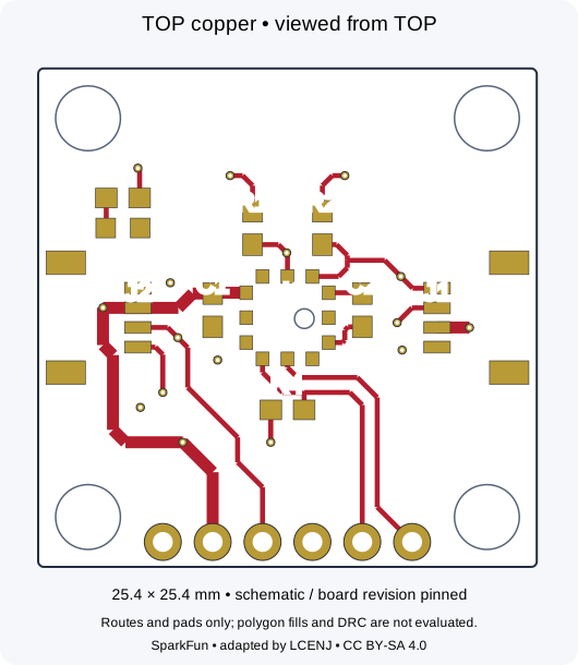
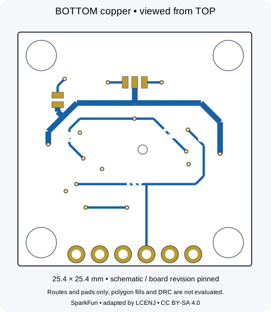
The file defines GND polygons on layers 1 and 16 and four ground vias. That is distinct from demonstrating a continuous, quiet return path on a manufactured board. These drawings reproduce routes, vias and pads; they do not solve copper pours or run DRC. During a redesign, inspect the ground return, the region beneath the sensor and separation from high-current switching in CAD, then measure the result. C1's presence alone does not establish supply quality over a long cable.
How the library obtains a sample
In src/SparkFun_MicroPressure.cpp, begin checks for an address response. Success establishes communication, not calibration or correct applied pressure. The default seven-bit address is 0x18. readPressure sends AA 00 00, waits using EOC or the BUSY flag, and reads four bytes: status followed by three data bytes. Memory-integrity and mathematical-saturation flags cause a NAN return. It would therefore be inaccurate to describe this library as having no error checks.
Two specific limitations remain in this revision. The EOC loop has no time deadline; polling likewise provides no bounded completion time for persistently valid BUSY status. The measurement-command endTransmission result and requestFrom byte count are also not checked before consuming the frame. These are observations of source code, not reproduced hardware failures. In the original example, calling readPressure separately for each printed unit requests a fresh measurement each time. To compare units for one sample, read once and convert that result.
A raw-number example with explicit units
For this model, the pinned library uses output endpoints 0x19999A and 0xE66666. An assumed raw code exactly halfway between them represents half the pressure range: 12.5 psi, or about 86.18 kPa. This is a worked calculation, not a sensor observation:
Ppsi = (raw − 0x19999A) × 25 / (0xE66666 − 0x19999A)
raw_mid = (0x19999A + 0xE66666) / 2
Ppsi = 12.5 psi
PkPa ≈ 12.5 × 6.89476 = 86.1845 kPa
A 24-bit output frame does not promise 24-bit measurement accuracy. Resolution, BFSL accuracy and total error under temperature and reference conditions are different quantities. Neither extra displayed digits nor a product-page accuracy headline establish the completed instrument's error. Subtracting an open-air absolute reading in software does not automatically create a precisely calibrated gauge-pressure sensor.
Proposed improvement: make a failed read explicit
For an instrument that must continue running when one sensor fails, add a bounded EOC/BUSY deadline, verify command completion and exact response length, and return a status separately from pressure. A 20 ms request deadline could be an initial design choice in light of the documented conversion of around 5 ms. It is not a guaranteed worst-case budget for every bus and host. The host's Wire implementation must also provide an effective bus timeout: a deadline outside a blocked bus call cannot interrupt that call.
The benefit is bounded system progress and a specific error report. Costs include more states and code, retry policy and the possibility of rejecting late data. Mark the sample invalid after failure and use a limited recovery policy rather than retrying indefinitely. Test the proposal with synthetic short responses, EOC stuck low, persistent BUSY and subsequent healthy responses. This proposal has not been applied to upstream code or qualified on hardware.
Bring-up and the limits of this review
On a test assembly, first check polarity and 3.3 V at the sensor, then the intended pressure reference, an appropriate open path and a leak-free tube connection. The datasheet specifies startup and supply-rise requirements; with a slow supply, evaluate controlled reset after stabilization. Contamination, incompatible media, solvents or excessive pressure can invalidate readings or damage the sensor. An Arduino example does not qualify this board for a safety or medical application.
The original Example1_BasicReadings compiled with library 1.0.1 and Arduino AVR Core 1.8.8 for the Uno target: 7,050 program bytes and 499 bytes of global variables. Warnings concerned unused parameters in the core's new.cpp. That target verifies a build only: an ordinary Uno uses 5 V logic, and direct wiring is not accepted here. Arithmetic was checked separately.
SparkFun owns the original project. Hardware and derived figures use CC BY-SA 4.0. The library's MIT LICENSE and its original Beerware/public-domain source-header notices are retained. The analysis and proposals do not imply participation in building or physically testing the project. The Qwiic OpenLog review continues the measurement path: obtaining a number and retaining a valid record are separate design problems.
Question and answer article
Ask your technical question
Questions and answers are published after moderation. Authors can see their own pending drafts.
No confirmed questions have been registered for this article yet.