How a UV sensor measures light: the VEML6075 circuit
A hardware review of SparkFun’s UV board: supply, I2C pull-ups, PCB, UV-index calculation, library error paths and calibration limits.
Contents
SparkFun's UV board turns light into digital readings, but a working connection is several steps away from a dependable UV index. The 3.3-volt supply, bus resistors, optical window, measurement interval and error handling all affect the result. This review follows the VEML6075 circuit and explains why its output should not automatically be treated as a calibrated measurement or a safety assessment.
The project belongs to SparkFun Electronics. The reviewed hardware commit e06622c2…, dated December 20, 2018, contains schematic, PCB and production files. The PCB carries a v10 marking. The official library is a separate repository: version 1.1.5 at commit c2e17899…, dated July 12, 2022. We inspected those revisions on November 6, 2026; that is an inspection date, rather than a build or hardware-test date.
Choosing a board for the project
The reviewed SparkFun SEN-15089 board is discontinued. For practical work, consider the VEML6075 module at Aftab Rayaneh; it is a different board, so use that module’s own supply specifications and pinout.
The sensor is a VEML6075 in a four-terminal OPLGA package measuring 2 × 1.25 × 1 mm. It is unsuitable for direct 5 V logic; the circuit in this article uses 3.3 V levels.
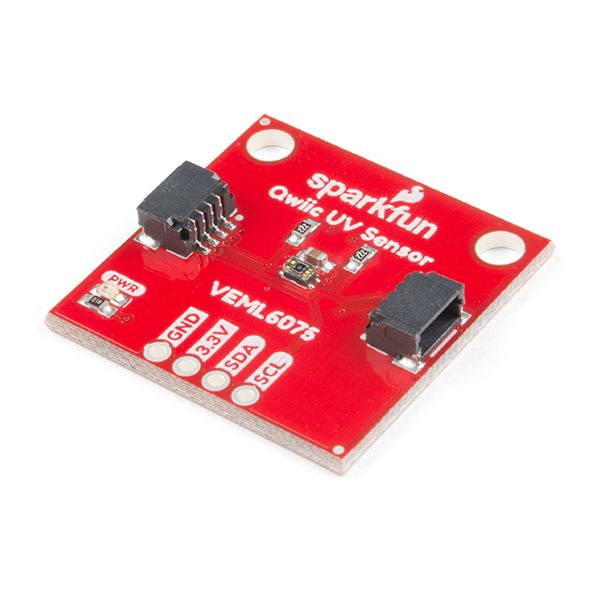
Are we reading light, or a number from a sensor?
Ultraviolet light is part of electromagnetic radiation. Wavelength describes it on a length scale; a nanometer is one billionth of a meter. The datasheet gives peak responses of 365 and 330 nanometers for the channels named UVA and UVB. These are not ideal band filters that integrate an entire spectral band, nor do two channels form a complete spectrometer.
Inside the part, a photodetector, amplification and analog-to-digital circuitry turn incident light into counts. Analog describes a continuous quantity; digital describes its numerical representation. Two compensation channels accompany the main channels, and software combines the readings to estimate a UV index. Sixteen-bit output resolution is not a guarantee of sixteen-bit accuracy or a direct measurement of risk.
This architecture keeps the host circuit small: the breakout does not need an external photodetector amplifier. The trade-off is dependence on the sensor's spectral response, optical conditions and conversion method. The Vishay datasheet in the pinned project, document 84304 revision 1.2, supplies the pin and electrical limits used here. Another PDF in that directory concerns the APDS-9301; it was excluded from this analysis.
Power: this is not a general-purpose 5-volt input
In the pinned schematic, the 3.3V net connects directly to U1 pin 4. The circuit contains no regulator or logic-level translator. The datasheet's supply and bus operating range is 1.7 to 3.6 volts. A Qwiic label does not authorize a 5-volt connection: the host and every pull-up must respect this sensor's limits.
C4, a 0.1 µF capacitor between supply and ground, supports local supply decoupling. A microfarad is one millionth of a farad, the unit of capacitance. That capacitor does not replace a stable source or sound cable design. Another supply branch runs through the 1-kilohm R3 and red LED D1 to ground. The LED indicates power in that branch, rather than successful I²C communication or valid sensing.
To estimate the indicator's cost, assume an LED drop of 2 volts solely for a calculation. Its branch current is then (3.3−2)/1000 = 1.3 mA. This is not a measurement, and actual forward voltage varies. The datasheet's example sensor current uses other conditions, including a 1.8-volt supply, so it should not simply be added to an LED estimate at 3.3 volts. The indicator can nevertheless become a substantial part of a battery-powered design's budget.
Data connections and pull-up resistors
I²C exchanges data using a clock line, SCL, and a data line, SDA. U1 pins 1 through 4 are ground, data, clock and supply respectively. On both J2 and J4, pins 1 through 4 instead carry ground, supply, SDA and SCL. Header J3 exposes those same four nets. The two sockets share one bus; they do not provide two independent sensors. Determine numbering from the actual connector drawing rather than a photograph's left and right.
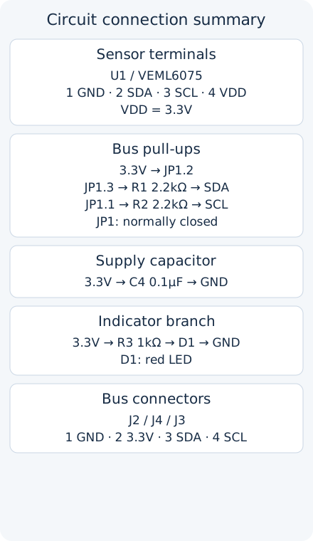
The sensor's data output is open-drain: it pulls the line low, while a resistor restores the high level. R1 on SDA and R2 on SCL are each 2.2 kΩ. Three-pad jumper JP1, labeled I2C, normally connects their supply sides to 3.3 volts. Its middle pad 2 is supply; outer pads 3 and 1 lead to R1 and R2 respectively. This jumper does not select an address. The sensor's seven-bit address is 0x10; simply chaining two same-address sensors does not make them independently selectable.
Ignoring actual low-level voltage, one low line draws approximately 3.3/2200 = 1.5 mA through its pull-up. Three identical enabled pull-ups in parallel become approximately 733 ohms and 4.5 milliamps per low line. Whether that is acceptable depends on the real devices' sink capability and low-level voltage requirements. The existing jumper permits removal of redundant pull-ups, but the bus still needs effective pull-ups somewhere. Our I²C, SPI and UART comparison explains the interface choices.
PCB layout and the optical path
The PCB file has a square 25.4-millimeter outline. U1 is centered at (12.7,12.7), while C4 is at (12.7,14.605). Their center-to-center distance is 1.905 millimeters, rather than the electrical path length of the capacitor connection. The sockets occupy opposite sides, the header is near the lower edge, and the I2C jumper is on the back.
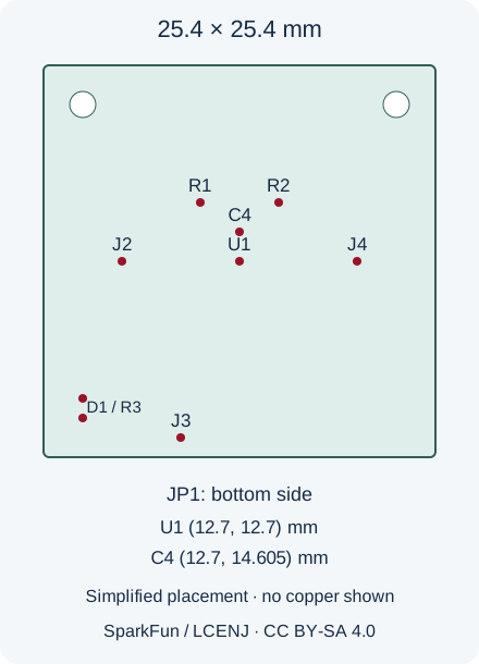
The ground net has polygons on layers 1 and 16 and four vias, which connect board layers. These objects show design intent, rather than measured noise performance or proof of the final filled copper everywhere. Inspect SDA, SCL, supply and LED return paths together with the ground plane in the actual CAD. Fabrication quality, grounding and bus behavior still require production-file checks and measurements on a sample.
The optical path matters as much as copper. An enclosure window, surface contamination, mounting angle or a shadow from a cable changes the light reaching the sensor. Material transparent to our eyes need not transmit UV suitably. Library coefficients labeled uncovered do not become an enclosure calibration merely because a window is added. Follow the datasheet's assembly requirements and avoid covering the optical surface with adhesive or unsuitable cleaning residues.
From 16-bit registers to a calculated index
A register stores a setting or reading inside the device. UVA comes from 0x07, UVB from 0x09, and compensation values from 0x0A and 0x0B. Each reading occupies two bytes, with the less significant byte first. The identifier register at 0x0C contains 0x26 for this model. After connecting, the library requests a default integration time of 100 milliseconds and normal operation. Integration accumulates the effect of light over an interval.
In the pinned library source, uva and uvb produce compensated counts; their names do not mean direct readings in optical-power units. For the normal 100-millisecond configuration and default coefficients, consider these entirely hypothetical inputs:
rawA=1000, rawB=800, comp1=100, comp2=50
A = 1000 − 2.22×100 − 1.33×50 = 711.5
B = 800 − 2.95×100 − 1.75×50 = 417.5
index = (711.5×0.001111 + 417.5×0.00125) / 2
index = 0.65617575
The result is approximately 0.656, but it is only this version's formula applied to invented inputs. Responsivity factors vary with configuration; the code supplies factors for 50-to-800-millisecond integration times and high-dynamic operation. Record the actual settings with the calculation instead of applying a universal manual multiplier. Example1 actually configures serial at 115200 and delays 250 milliseconds between iterations; its old introductory 9600-baud comment disagrees with the executable instruction. That delay guarantees neither simultaneous channel acquisition nor readiness of every reading.
A concrete error-path limitation and a proposed change
In this revision, rawUva and similar raw-reading functions return an unsigned 16-bit value, but return a negative error code when a read fails. A return value of −4 becomes 65532 in that type. In addition, readI2CBuffer does not compare requestFrom's returned byte count with the required two bytes. These are source-level findings; we did not unplug a real cable and observe the resulting device behavior.
Our proposed change separates status from data, rejects short reads and retains all four readings with settings and timing as a valid or invalid set. The cost is an API change and updates to consuming applications. The benefit is avoiding a communication failure masquerading as a numeric sample. A proposed verification is to inject a communication failure and a one-byte response in a test environment, and confirm that no valid index is published. If a common exposure cycle matters, verify trigger handling and the required waiting interval against the datasheet and actual behavior too.
For a lower-power hardware revision, an optional disconnect for the LED branch is a separate proposal: existing JP1 controls I²C pull-ups only. Compare its benefit with measured current and the need for an indicator. For the optical path, define a fixed window and mounting arrangement and compare against an appropriate reference under several conditions. A displayable number does not substitute for a calibration reference.
Bring-up and the limits of this review
On a test unit, establish supply, connector orientation and logic levels from that board's documentation first. Then record address and identifier checks, configuration and successful reads separately. Inspect illumination, data age, saturation and response to communication loss. Changing an unknown lamp or observing a steady value behind a window is not, by itself, calibration. Do not substitute this sensor and formula for a validated personal-protection instrument or a safety-control system.
Continue with accuracy and calibration for the distinction between counts and measurement quality, or the oscilloscope and logic-analyzer lesson for observing bus behavior.
The repository licenses hardware under CC BY-SA 4.0, and the derived drawings use that license. Its library LICENSE says MIT for code, while the cpp header refers to GPL and the example header to Beerware. We do not present those inconsistent notices as one unambiguous license, and upstream code is not redistributed in this article. SparkFun and the original creators retain attribution; the analysis and proposals are LCENJ editorial work, without claiming to have built or contributed to the project.
Question and answer article
Ask your technical question
Questions and answers are published after moderation. Authors can see their own pending drafts.
No confirmed questions have been registered for this article yet.