Changing Frequency or Coding Phase: FSK and PMCW Radar Explained
FSK switches among frequencies; PMCW follows a phase code. Two tones and a four-chip teaching sequence explain range information and ambiguity.
Contents
Radar from zero — part 4 of 6
FSK and PMCW add distinguishable structure to a transmitted signal in different ways. FSK uses selected frequencies; PMCW follows a phase sequence. Their structure can provide delay and range information, but only with appropriate processing, calibration and ambiguity handling.
This lesson connects everyday situations with calculations. Numbers use the stated assumptions.
Frequency and phase are different controls
Frequency counts cycles per second. Phase describes the position within a cycle at a particular instant, like the position of a clock hand. One full turn is 360 degrees or 2π radians.
FSK means Frequency Shift Keying: switching among specified frequencies. PMCW means Phase-Modulated Continuous Wave: changing carrier phase according to a code. Rapid phase changes also create bandwidth; PMCW is not a bandwidth-free single tone.
FSK: compare two repeating rulers
In a simple two-frequency model, compare echo phase at f1 and f2. After circuit phase is calibrated, and provided both observations belong to the same target, their difference is range-related: Δφ≈4πΔfR/c, with a defined sign convention.
A common motion-oriented FSK implementation tracks the phase of Doppler signals at two frequencies. That does not mean every FSK module can range every stationary target. More elaborate multi-frequency methods exist; the actual output and hardware documentation determine the capability.
Two frequencies separated by one megahertz
Assume Δf=1 MHz and R=3 m. The ideal phase difference is about 0.1257 radians, or 7.2 degrees. It must be distinguished from circuit phase error, noise and target motion between observations. A simple equation does not make every distance easy to measure.
Phase repeats every full turn, so this two-tone model repeats after c/(2Δf)=150 m. That is an ambiguity period, not a promise of 150-metre detection range. Increasing frequency separation tenfold increases phase sensitivity tenfold while reducing this period to 15 m. Multiple targets also complicate echo association.
FSK: Deltaf = 1e6 Hz, R = 3 m
Deltaphi = 4 pi Deltaf R/c ~= 0.12566 rad = 7.2 deg
ambiguity period = c/(2 Deltaf) = 150 m
PMCW toy: 2 chips x 10 ns = 20 ns -> R = 3 m
PMCW places a signature on phase
A simple binary PMCW sequence can select zero or 180-degree phase in each code interval, represented by +1 and −1. Each interval is a chip; here that word means a time interval, not a silicon component.
The receiver compares shifted copies of a reference code with the received sequence. Multiplying and summing these sequences is correlation. A matching delay produces a peak. Real pulse shapes, filtering, Doppler and other echoes change the peak and sidelobes.
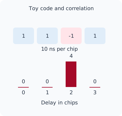
A four-chip example you can check by hand
For teaching only, use [+1,+1,−1,+1], with each chip lasting 10 ns. Delay an ideal echo by two chips. Four-point circular correlation gives 4 at the matching shift and zero at the other three shifts. The downloadable exercise performs the multiplication and summation.
Two chips mean 20 ns and a monostatic range of 3 m. The full code lasts 40 ns; repeating it makes delays separated by four chips indistinguishable in this model, corresponding to a 6-metre range period. This tiny code is not a proposed practical radar. The example has no noise, physical pulse shaping or radio channel.
From clean examples to real systems
A longer code can extend the repetition period, and combining observations can help detection, at the cost of observation time and processing. Different codes do not guarantee that radar interference disappears. Code properties, synchronisation, Doppler, receiver dynamic range and sidelobes must be evaluated together.
Choose a method by asking whether targets are stationary or moving, how many simultaneous targets matter, and what ambiguity interval and response rate are required. This lesson claims no universal superiority for FSK or PMCW and includes no RF or interference experiment.
Download the calculation
Run the Python exercise with Python 3.10 or later. It needs no extra libraries, device or network connection. The output below comes from these hypothetical calculations.
FSK phase=7.2 deg; ambiguity period=150 m
toy circular correlations=[0, 0, 4, 0]; peak at 2 chips -> 3 m
Calculated hypothetical examples only; no hardware, RF or measured-data test.
Primary sources and further reading
The explanation and examples are original editorial teaching material. These primary references support the physical principles and processing models.
Question and answer article
Ask your technical question
Questions and answers are published after moderation. Authors can see their own pending drafts.
No confirmed questions have been registered for this article yet.