Overcurrent and short circuits: why each branch needs protection
Understand supply current limits, branch protection and fuse selection with a worked four-load, 24 V example and a practical planning exercise.
Contents
A branch fuse is intended to deal with a fault in its own path; a power supply's current limit responds to the combined load. A protected supply therefore does not automatically protect every small branch wire. Four outputs marked 2 A do not establish that the system can deliver 8 A. A useful design accounts for normal consumption, startup, fault response and disconnection time together.
Imagine sensors, a controller and lights sharing one supply. If a lighting cable is damaged, the aim is to disconnect that path while keeping the controller running, provided the supply and protection can support that behavior. The following hypothetical low-voltage example explains the calculations and the missing measurements. It is a conceptual lesson, not a control-panel installation drawing or an instruction to create a short circuit.
Start with voltage, current and power
Voltage is the electrical potential difference between two points, measured in volts. Current is the rate of flow of electric charge, measured in amperes. A load, such as a lamp or a sensor board, draws current according to its circuit and operating conditions. A hypothetical supply marked 24 V / 5 A has a nominal output of 24 V and a nominal ability to supply 5 A under stated conditions. It does not force 5 A through every connected board.
Power is the rate of energy transfer, measured in watts. For a steady DC path—direct current with fixed polarity—P = V × I gives a useful power budget. The nominal product here is 24 × 5 = 120 W. Temperature derating, cable drop and any simultaneous-output restrictions still have to be checked in the actual product documentation.
Overload and short circuit are different fault conditions
An overload occurs when a path carries more current than its allowed operating value. A stalled motor may draw much more than usual even though its connections have not changed. A short circuit is an unintended low-resistance path, for example when damaged insulation allows two conductors to touch. Both can produce overcurrent, but their causes, severity and duration differ.
Short-circuit current is not infinite. A simple hypothetical 24 V source across a total resistance of 0.2 Ω would demand 24 / 0.2 = 120 A. That is not a prediction that a real 5 A supply delivers 120 A: path resistance, stored capacitor energy, supply impedance and current limiting shape the actual pulse. Phoenix Contact's device circuit-breaker basics explains fault types and coordination between supply and protection.
Why the supply's protection may miss a branch problem
A branch is a path from a shared supply to a particular load or group. In response to excessive total current, a supply may limit current, reduce output voltage, or shut down and periodically restart. If it monitors only the total, one branch could exceed its wire's capability while the combined load remains below the supply limit.
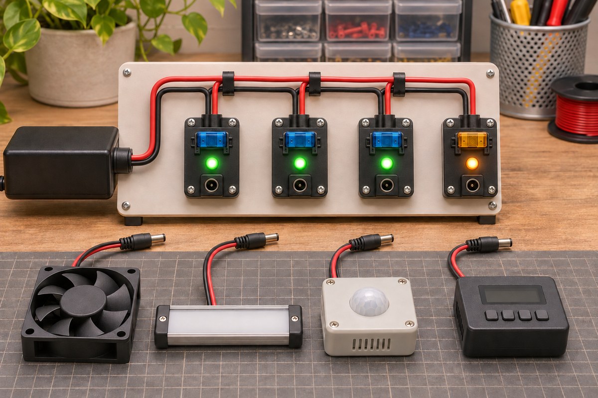
Branch protection brings the response to the individual path. Selective disconnection means the faulty path is removed without unnecessarily disconnecting healthy paths. This needs coordination: the supply must support healthy loads during fault clearing, and upstream protection must not shut everything down first. Trip behavior, cable characteristics and the supply's transient capability matter together. Four switches or four status indicators do not demonstrate that coordination.
A four-branch, 24 V worked example
Assume the supply delivers its nominal 24 V and 5 A at the chosen operating point. The following steady loads are hypothetical teaching values, not specifications for an advertised product.
| Branch | Assumed current | Power at 24 V |
|---|---|---|
| Sensor group | 0.5 A | 12 W |
| Controller | 1 A | 24 W |
| Lights | 1.5 A | 36 W |
| Fourth load | 1 A | 24 W |
| Total | 4 A | 96 W |
The nominal difference is 1 A, or 24 W. This is arithmetic headroom, not guaranteed margin at every temperature or during transients. If the fourth load draws 3 A instead of 1 A while starting, total demand becomes 0.5 + 1 + 1.5 + 3 = 6 A. Knowing that steady consumption is 4 A is insufficient to approve simultaneous startup.
Now suppose all four protection channels carry a nominal 2 A marking. Those markings add to 8 A, but they do not turn the 5 A supply into an 8 A supply. Nor does a nominal 2 A value imply disconnection at exactly 2.001 A. Protection type, tolerance, time and temperature affect what happens.

Will the three healthy loads remain running?
Suppose, as a separate hypothetical fault case, electronic protection holds branch four at 3 A before turning it off. The healthy branches still require 3 A, so temporary demand is 6 A. A 5 A supply's nominal rating alone does not establish that voltage remains stable during this interval. Once branch four is completely disconnected, steady demand returns to 3 A, or 72 W.
There are two separate questions: does the faulty path disconnect in time, and do the healthy loads survive the transient without resetting? The second depends on trip time, voltage dip, each load's reset threshold and supply behavior. The lesson on ESP32 power and brownout troubleshooting explains related power problems. Adding currents does not replace measuring the fast voltage event in the actual circuit.
A melting fuse needs more than an ampere rating
A conventional fuse opens when its internal element heats and melts; after operation it normally needs replacement. Compare normal current and startup pulses against the selected series' time-current information. This describes how long an overcurrent may persist; even a fast-acting fuse does not have zero clearing time.
The voltage rating must be suitable for DC and the actual circuit voltage. Interrupting capacity must suit the available fault current; it is different from nominal current. Ambient temperature, holder, wire and installation conditions also matter. The Littelfuse Fuseology selection guide brings these criteria together. Do not treat a derating factor for one family as a universal rule. Without load, conductor and device data, “fit a 2 A fuse” is an incomplete recommendation.
What an electronic fuse can add
Electronic protection can measure current and control a semiconductor switch. Current limiting still permits current to flow; disconnection turns the path off. Some devices control the output-voltage rise to reduce initial charging current. The actual model and configuration determine the available functions: the word eFuse alone guarantees none of them. ST's eFuse overview explains the mechanism and family options.
After a fault, some devices automatically retry and others remain off until reset. Automatic retry means that the load may become powered again without operator intervention. Latch-off requires a recovery decision. Texas Instruments' discussion of fault recovery explains the distinction. Thermal protection of the switch itself does not establish cable health or process safety.
Add heat and startup to the calculation
For an assumed path resistance of 0.25 Ω, dissipation at 2 A is I²R = 2² × 0.25 = 1 W. At 4 A it becomes 4 W. Doubling current produces four times the heating in this model. Resistance varies with temperature, and this calculation does not determine a permissible wire temperature; it shows why the weakest part of the current path matters.
An input capacitor also charges at startup. If a hypothetical 470 µF capacitor rises linearly from 0 to 24 V in 10 ms, its average charging current from I = C × ΔV / Δt is 1.128 A, in addition to the load current. This simplified model does not predict the actual peak or a trip time. Checking startup before raising a protection setting helps distinguish normal inrush from a persistent fault.
Move from a worksheet to a defensible test
Before choosing a device, record each load's steady and starting currents, conductor and connector capability, required voltage and intended fault-recovery behavior. Read the supply's overload response and the protection device's tolerances and timing. The datasheet-reading lesson helps distinguish damage limits from operating conditions.
Physical verification needs suitable equipment and an appropriate procedure. Start by checking normal consumption and voltage drop without inducing faults. Protection testing requires a controlled test load, limited energy and a procedure suitable for the equipment. Do not deliberately short wires for this lesson. Record branch and input currents, healthy-load voltage dip, disconnection time and restart behavior separately. Current measurement, as covered by the INA169 analysis, is only one tool; the measurement circuit is not itself a current-disconnecting protector.
Exercise: give a number and a reason
Keep the hypothetical 24 V, 5 A supply, but change steady branch currents to 0.4, 0.6, 1.2 and 0.8 A. Calculate the total and power. If branch three reaches 3 A while starting, what is temporary total demand? Is being below 5 A sufficient to approve startup?
The steady total is 3 A and power is 72 W. During the assumed start, total demand is 0.4 + 0.6 + 3 + 0.8 = 4.8 A; supply transient data, cable information and startup duration are still needed. If branch four is limited to 3 A during a fault, temporary demand is 0.4 + 0.6 + 1.2 + 3 = 5.2 A. After it disconnects, 2.2 A and 52.8 W remain. Finally, name three missing inputs for choosing a real fuse, such as conductor capability, time-current behavior and interrupting capacity. These are calculated answers.
Sources and scope
Phoenix Contact's Device circuit breakers—the basics, document 52003890/2013-02-01/00, particularly printed pages 5, 9, 12 and 13; the Littelfuse Fuseology selection guide, whose supplied file includes copyright pages dated 2014 and 2015, particularly its selection and curve sections; ST's eFuse overview; and TI article SSZTB89, June 2016. To select protection for your equipment, apply these principles to its supply, conductors, loads and the chosen device’s curves.
Question and answer article
Ask your technical question
Questions and answers are published after moderation. Authors can see their own pending drafts.
No confirmed questions have been registered for this article yet.