What is SLAM? Localization and mapping with a worked example
Understand pose, reference frames, drift, loop closure and sensor choices. Work through a rectangle example and distinguish endpoint error from trajectory accuracy.
Contents
SLAM estimates a moving device’s position and its surroundings at the same time. The device follows its motion, observes the environment and compares new observations with its developing map. It then revises both estimates. The result is a map and a pose with uncertainty, rather than an error-free coordinate system. Understanding observations, movement and reference frames makes the process much easier to follow.
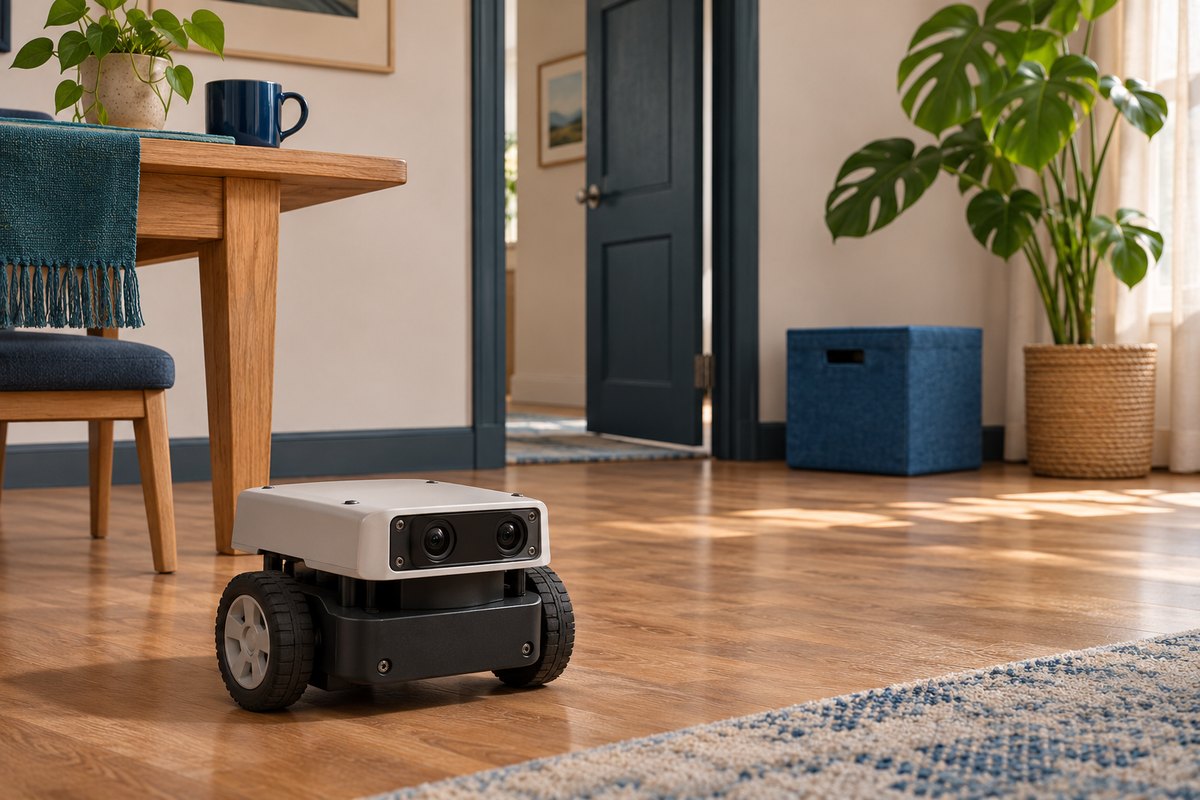
Why do the map and the device’s location depend on each other?
Imagine entering an unfamiliar room. Saying “I am beside the door” requires identifying the door and locating yourself relative to it. Without an existing map, further observations and movement gradually reveal the relationships between you, the door and other objects. The name Simultaneous Localization and Mapping describes that linked estimation problem.
Distinguish three tasks. Localization in a known map estimates the device’s location within an existing map. Mapping with a known trajectory places observations using known sensor positions. In SLAM, both are unknown and must be estimated together. The MathWorks SLAM overview explains this connection between motion and environmental estimates.
Position, orientation and reference frames
Position describes where an object is; orientation describes which way it faces. A camera can rotate left without leaving its spot. Together, position and orientation form a pose. On a flat floor, a simplified pose can use three numbers: x, y and heading. Three-dimensional motion also needs height and additional rotations.
A position is incomplete without its reference frame. In this lesson’s paper example, the starting point is the origin, x points right and y points up the page; distances are in metres. This drawing convention is separate from a robot’s body axes. ROS REP 103 uses forward, left and up for conventional body axes, while optical camera axes follow another convention. Combining observations requires knowing the transformation between those frames.
Record angular units too. Ninety degrees is a quarter-turn, equivalent to π/2 radians. A function expecting radians will interpret the number 90 very differently. Convert metres, centimetres and milliseconds into compatible units before calculating. These basic checks can prevent a coordinate error from looking like a mysterious failure of the mapping algorithm.
How do observations become a map?
A sensor supplies observations: a camera provides images, lidar provides sets of ranges and motion sensors provide movement information. One stage of the software tries to relate consecutive observations, for example by matching recognizable corners between images. These relationships help estimate a change in pose. The new observation is then considered alongside earlier estimates.
An image feature need not have an object’s name. A stable corner on a frame can be more useful for matching than the label “door.” Nor does every SLAM method rely only on corner features. The Visual SLAM documentation separates matching, pose estimation, map points and refinement. A sparse feature map, a detailed three-dimensional model and an occupancy grid are different representations, rather than equivalent outputs.
For a simple geometric example, put a robot at the origin facing along x. An ideal one-metre forward movement ends at (1,0). If it first turns ninety degrees toward y and then moves one metre forward, it ends at (0,1). “One metre forward” does not always mean adding one to x: the device’s orientation determines how a movement relates to the fixed reference.
Why does a motion estimate gradually drift?
Odometry follows relative movements and accumulates them to estimate a trajectory. Its information can come from wheels, images or combined sensors. Small movement errors can accumulate over time; this gradual departure is called drift. Wheel slip or an incorrect image match can increase the difference between the estimated path and the actual one.
REP 105 offers a useful distinction: odom provides a continuous local reference that can drift, while map provides a global reference in which a localization correction can cause a jump in the reported pose. These are different reference frames with different roles. Smooth local movement estimates and corrections to overall location serve different needs.
A worked example: following a rectangle
Start a hypothetical geometric path at (0,0): two metres right, one metre up, two metres left and one metre down. The displacements sum to zero, so the path returns to the origin. Now suppose the device reports an endpoint at (0.15,0) metres. That endpoint is 0.15 metres, or 15 centimetres, from the start. These numbers are invented for the example.
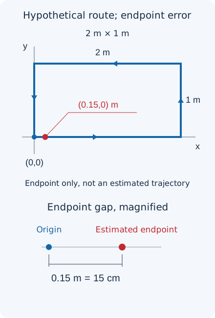
This calculation describes endpoint error only. An estimated trajectory could wander far away midway through the route and later return close to the start. Endpoint distance also says nothing about final orientation error. A fuller evaluation compares several poses along the trajectory with a reference, after ensuring compatible units, times and coordinate frames.
What does loop closure correct?
Recognizing a place seen earlier can provide a new constraint connecting two parts of a trajectory. Detecting and using that return is called loop closure. Instead of relying indefinitely on accumulated movement estimates, the software tries to make its path and map consistent with the revisit observation.
The correction need not move only the final point to the origin; earlier poses and map points may change too. Similar-looking corridors or doors can produce false matches, so appearance must be checked against geometric consistency. Forcing an endpoint to zero in a drawing does not establish successful SLAM or demonstrate accuracy.
How does the sensor choice limit the result?
The sensor-data workflow guide explains that a monocular camera without additional information cannot determine absolute scene scale. More information is needed to express its map in metres. Stereo uses two images and a known separation between cameras; an RGB-D camera supplies depth alongside color. Calibration includes determining camera parameters and the geometric relationship between sensors.
An inertial measurement unit, or IMU, commonly contains an accelerometer and gyroscope. It does not provide a ready-made, error-free position: acceleration measurements include gravity, and errors accumulate during integration. Adding an IMU without geometric calibration and timestamp alignment does not automatically improve a result. Lidar provides range information, but surfaces and environmental conditions still affect which sensor works well.
Write down the requirements before choosing a model. Is the environment bright or dark? Do surfaces offer enough texture? Is motion rapid? How much memory and processing capacity are available? These questions help more than simply choosing the most expensive sensor. ORB-SLAM3 from UZ-SLAMLab is an example of a research implementation supporting multiple input configurations; knowing a library’s name does not establish that it is ready to run on every embedded board.
From a map to dependable motion
SLAM alone does not generate a safe route or motor commands. Other components manage a destination, obstacles and movement. The Nav2 guide to navigating while mapping shows how these components work together. A stable map display does not establish that a moving obstacle has been detected.
For a real prototype, first make observations inspectable: retain timestamps, reference frames, sensor settings and tracking status. If the map becomes distorted after turns, check data timing, frame transformations and image blur before changing algorithm settings. Changing several parameters together makes causes harder to isolate. Our lesson on sensor accuracy and calibration distinguishes measurement quality from numerical resolution.
Exercise: what can you actually conclude?
Assume an estimated endpoint of (0.12,0.05) metres. Calculate its distance from the origin, then decide whether that distance establishes error at every point or final heading error. Next, imagine a device announcing loop closure in a corridor with two similar doors. What additional evidence would you require?
Answer and reasoning
Pythagoras gives √(0.12²+0.05²) = √0.0169 = 0.13 m, or 13 centimetres. We have no other data for intermediate-position or orientation errors. A similar door alone does not establish a revisit: several observations and their geometric relationships must agree with the trajectory. This is a paper calculation and reasoning exercise, rather than an algorithm execution or robot test.
Question and answer article
Ask your technical question
Questions and answers are published after moderation. Authors can see their own pending drafts.
No confirmed questions have been registered for this article yet.