Inside Weather Shield V1.2: from sensor circuits to useful weather data
Weather Shield puts humidity, temperature, pressure and light sensors on one board. Following its power paths, interfaces and firmware reveals how calibration, layout and error handling affect the results.
Contents
A weather station needs more than a collection of sensors. You need to know where each number came from, how the electronics receive power, and whether the instrument’s own heat is changing the air it measures. SparkFun’s open-source Weather Shield makes those decisions visible. It reads humidity, temperature, pressure and light, with connections for external rain and wind instruments. Its most useful lesson is the gap between obtaining a number and making a trustworthy measurement.
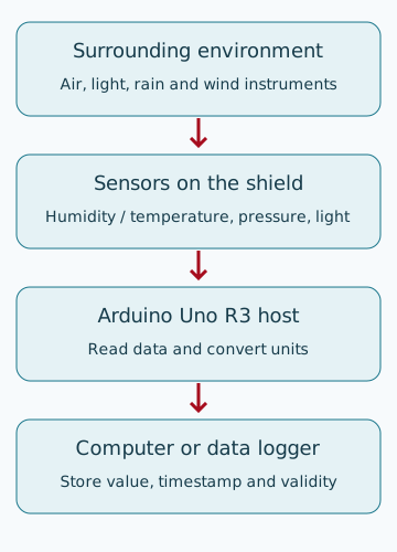
A shield is an add-on circuit board that plugs into a host board. Here the host is an Arduino Uno R3: it runs the program, reads the sensors and sends results to a computer. The shield does not contain a separate processor running this application. This review follows SparkFun Electronics’ project at commit 77a360d0d9738a20ad49a2e2dd14cfd86bb9a7ed, dated 4 July 2023. The review date is 25 October 2026.
Board availability and the version that matters
The reviewed hardware is the complete DEV-13956 Weather Shield V1.2, in the Uno shield form factor, using a Si7021 humidity sensor. The earlier DEV-12081 used an HTU21D and is a different version. On 25 October 2026, SparkFun’s direct product page marked DEV-13956 retired and out of stock; DigiKey’s page for the same board marked it obsolete. These are identification and availability references, not a claim that the board can currently be ordered.
Regional availability — Iran: no matching direct Iranian product page for this exact board and revision was verified. Local stock is unconfirmed. A separate Si7021 breakout, BMP280 module or unspecified weather kit is not an identical replacement. You can follow the analysis without purchasing hardware; the design files and worked examples expose the important decisions.
The problem and the role of each block
Imagine logging the conditions in a small equipment shelter. Has the air become warmer or more humid? Has pressure fallen, or has only the light reaching the instrument changed? A sensor converts an environmental quantity into an electrical output. The host program reads that output and presents it with a unit. The distinction is explained in analog versus digital sensors.
| Block in the V1.2 files | Role and connection | What the result means |
|---|---|---|
| U5: Si7021, six-pin DFN package | Relative humidity and temperature, powered at 3.3 V and read over I²C | Relative humidity depends on temperature. A 50% reading means half the saturation level at that temperature, not that half the air volume is water. |
| U4: MPL3115A2, LGA8 footprint | Absolute air pressure and temperature over I²C | Local absolute pressure is not sea-level-corrected pressure. Chip temperature need not equal free-air temperature. |
| U3: ALS-PT19, with 10 kΩ resistor R10 | Converts light-dependent current into a voltage read at A1 | The example reports voltage. It does not produce lux without a valid conversion model and calibration. |
| Optional rain and wind connections | Wind direction at A0, wind speed at D3 and rain at D2 | Conversion factors and errors depend on the external mechanical instrument, wiring and contact-bounce handling. |
| U6 regulator; Q1 and Q2 level shifters | Provide a 3.3 V supply and connect the sensors to a 5 V host | I²C level shifting does not make every board input compatible with any 3.3 V host. |
These connections come from the schematic at the pinned commit. U5 is labelled only SI7021; the ordering suffix, grade and A10/A20 revision of an assembled device are not specified. The project’s linked data sheet is Si7021-A10 revision 1.0. Specifications for an A20 or a similar breakout should not automatically be assigned to an unidentified physical part.
Follow the power nets before changing the program
Voltage is a difference between two electrical points; here the readings are relative to the shared ground, GND. In the schematic, VIN feeds both IN and EN on regulator U6. Its output supplies the 3.3 V sensors, the optional GPS supply and reference input A3. C13 and C14 are 10 µF capacitors at the regulator input and output respectively. Smaller capacitors near the sensors supply short local current demands.
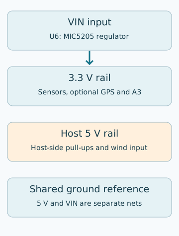
A separate host 5 V net supplies the host-side I²C pull-ups, the wind-direction pull-up and the input clamp diodes. The Uno header’s 3.3 V pin is not connected to the shield supply net in this file. Consequently, a powered host or a working USB serial port does not prove that shield VIN and then its regulated 3.3 V rail are present. Measure these three points against ground first; host boards and clones can have different power paths. Do not bridge VIN to 5 V or join supplies without checking how current can flow back through them.
The embedded component library identifies U6 as a fixed 3.3 V MIC5205-family regulator in SOT-23-5; it does not provide a full ordering suffix. Pin 1 is IN, 2 GND, 3 EN, 4 bypass and 5 OUT. The MIC5205 data sheet specifies a 150 mA nominal output capability, but that is not permission to draw 150 mA at every input voltage and ambient temperature. Preserve the regulator’s output-capacitor stability requirements when substituting parts; equal capacitance alone does not justify replacing tantalum with ceramic.
A worked heat estimate
A linear regulator turns most of the input-to-output voltage difference into heat. Assume a 9 V input and a total 50 mA output load. Ignoring regulator ground current for this first estimate:
P ≈ (VIN − VOUT) × I
P ≈ (9 − 3.3) V × 0.050 A = 0.285 W
ΔTJ ≈ 0.285 W × 220 °C/W = 62.7 °C
The 220 °C/W value is the data sheet’s junction-to-ambient thermal resistance under its stated mounting conditions. The calculated 62.7 °C rise concerns the regulator’s internal junction under those assumptions. It is not a measurement of this board, a predicted sensor temperature or a guarantee of acceptable operation. Copper area, actual current, ground current and enclosure conditions change the result. The design implication is still clear: do not trap the air sensor next to a heat source. Linear-regulator power loss develops this calculation further.
Why the I²C lines need level shifting
I²C connects several devices using two lines. SDA carries data and SCL provides its timing. Devices generally pull a line low; a pull-up resistor brings it high again. These sensors run at 3.3 V, so directly pulling their signal lines up to 5 V would be the wrong connection.
Q1 and Q2 are BSS138 N-channel transistors in SOT-23. Both gates connect to 3.3 V, their sources to the sensor side and drains to the host side. R3/R4 serve SDA and R2/R5 serve SCL, each 4.7 kΩ, with a pull-up on each voltage domain. The host side reaches A4/SDA and A5/SCL. The humidity sensor uses seven-bit address 0x40, and the pressure sensor uses 0x60. Finding an address verifies a response, not measurement accuracy.
For a first estimate, assume 100 pF capacitance on one side of the bus. The approximation tᵣ ≈ 0.8473RC gives about 398 ns with a 4.7 kΩ pull-up. That is below the 1000 ns Standard-mode rise-time limit but above the 300 ns Fast-mode limit. “There are only two sensors, so use 400 kHz” is therefore not a justified conclusion. The transistor, cables, parallel pull-ups and actual capacitance must be included when measuring the edges; this simple calculation does not validate the complete bidirectional bus. The timing reference is NXP’s I²C specification, UM10204. See also choosing a 3.3 V/5 V level converter.
Turning readings into useful units
Pressure and humidity: digital paths
A digital sensor performs some conversion and compensation internally. The example puts the MPL3115A2 in barometer mode and selects 128-times oversampling: the device takes more samples to form a result. This also takes time; the data-sheet table lists about 512 ms for that setting. A nominal once-per-second report does not mean that all the sensors were sampled simultaneously.
For a hypothetical pressure result of 99850 Pa, dividing by 100 gives 998.5 hPa. This changes the unit only; it does not correct for the site’s altitude. Comparing it with a weather app displaying sea-level pressure can be misleading unless both reference conventions are known. The MPL3115A2 data sheet distinguishes absolute pressure, altitude output and conversion settings.
The Si7021 provides relative humidity and temperature. The Basic example prints temperature in Fahrenheit. Use °C = (°F − 32) / 1.8 or the appropriate library function for Celsius. A difference between the humidity sensor’s temperature and the pressure sensor’s temperature does not by itself identify a faulty chip. Location, board heating and response time can differ. Investigate those causes before applying a numerical correction to an air-temperature reading.
Light and supply voltage: analog paths
On an analog input, the Uno converts voltage to a number using an analog-to-digital converter, or ADC. The usual Uno R3 reading runs from 0 to 1023. More light makes the ALS-PT19 pass more current; R10 turns that into a voltage at A1. Light-to-current response, linear range and illumination spectrum have conditions in the ALS-PT19-315C/L177/TR8 data sheet. The design file only says ALS-PT19, so the full suffix of a fitted part requires separate confirmation.
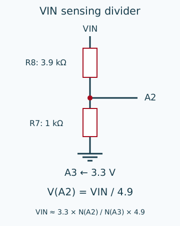
To reduce sensitivity to a changing ADC reference, the example measures the 3.3 V rail at A3 and takes a ratio. VIN uses a divider: upper resistor R8 is 3.9 kΩ and lower resistor R7 is 1 kΩ. A2 therefore sees VIN divided by 4.9. Suppose three consecutive readings are:
N(A3) = 675     N(A1) = 205     N(A2) = 376
Vlight ≈ 3.3 V × 205 / 675 = 1.002 V
VIN ≈ 3.3 V × 376 / 675 × 4.9 = 9.007 V
The first result is approximately one volt, not one lux. Reporting lux requires a valid conversion and application-appropriate calibration. BH1750 and the meaning of lux illustrates the alternative of a digital light meter. A BH1750 is not a pin-compatible replacement for ALS-PT19; using it changes the circuit and firmware.
Ratios do not remove every error. If the supposed 3.3 V rail is actually 3.25 V while the program still assumes 3.3 V, the resulting scale error is about +1.54%. R8 and R7 have 1% component specifications in this schematic; the code comment calls them 5% parts. Even with 1% parts, the worst resistor combinations alone produce approximately −1.58% to +1.60% error in the reconstructed input voltage. ADC and reference errors remain separate. See accuracy, resolution and calibration.
Rain and wind need more than a connected cable
The design includes two RJ11 footprints whose reference names end in DNP: their presence in the PCB does not mean the connectors are fitted. The mechanical rain and wind instruments are external. RAIN, WSPEED and WDIR have 1 kΩ series resistors and diode pairs to ground and 5 V. These provide current limiting and clamp paths. The library’s BAS16 label is not evidence of lightning protection, industrial surge immunity or unlimited cable length. The file uses SOD-323 diode footprints; any build needs an explicit purchased-part, symbol and footprint match.
The wind vane uses resistors and mechanical contacts; its measured voltage identifies a direction. The Weather Station example explicitly sets the Weather Meter library to a ten-bit ADC. Keep that setting for the Uno R3. Moving to a 12-bit or 3.3 V host without reviewing the divider and thresholds can change the decoded direction. The manufacturer’s guide recommends a 5 V host for this wind instrument. An I²C level shifter does not solve that analog compatibility issue.
What the board layout reveals
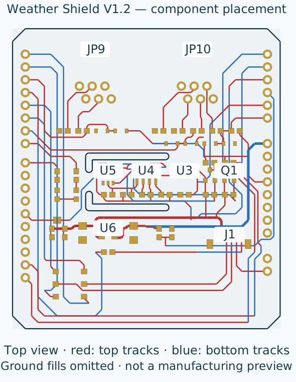
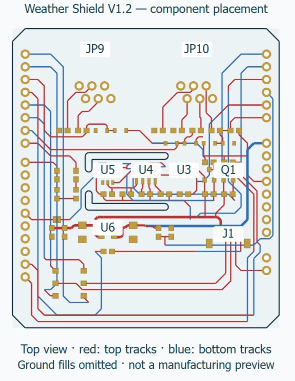
In the PCB file, humidity sensor U5 is at (19.05, 30.48) mm, pressure sensor U4 at (26.67, 30.48) mm and regulator U6 at (19.05, 19.05) mm. Routed slots are present around the sensor region in the board-outline layer. Thermal isolation is already part of the design, rather than a new suggestion in this review. Slots still cannot eliminate heat transfer through the air or enclosure.
Ground polygons are defined on both copper layers. Their presence does not prove that every return path remains continuous; inspect the filled output and actual current paths. Local capacitors sit near the sensors and the level-shifting network is grouped by the digital interface. Optional wind and rain connectors are near the upper board edge. External cables need strain relief and a suitable return path; connector solder joints should not carry cable tension.
An outdoor version needs a housing that excludes water while allowing appropriate air exchange. A humidity sensor sealed in an airtight box is not necessarily measuring outdoor humidity. Sunlight and heat from the host underneath the shield can also shift the readings. Select the enclosure, ventilation and protective materials for the actual sensor and conditions, then compare with a reference. Final weather-measurement error cannot be inferred from the PCB file alone.
Which firmware combination was checked?
Two original sketches compiled without changes to the project source for arduino:avr:uno, using Arduino AVR core 1.8.8. The dependencies were Si7021 1.0.5, MPL3115A2 1.2.4 and Weather Meter Kit 1.1.2. Basic used 8138 bytes of flash and 673 bytes of global variables; Weather Station used 9136 and 752 bytes respectively. Compiler warnings remained. These figures describe this recorded combination, not a reconstruction of the manufacturer’s historical release binary.
The manufacturer’s V1.2 guide also warns that newer Si7021 library versions break these examples and that this guide’s I²C libraries have issues on the Uno R4. Installing the newest version of every dependency is not necessarily a reliable starting point for an older project. Begin with Basic V12; Weather Station V12 adds the mechanical instruments. The GPS example is outside this article’s compilation and behavioral-review scope.
Specific improvements worth testing
These proposals follow from reading the files; they are not fixes validated on a physical sample. Change and assess one factor at a time so that the cause of an improvement or regression remains visible.
| Evidence and problem | Proposed change and cost | How to assess it |
|---|---|---|
| get_light_level and get_battery_level divide by A3 without checking for a zero or invalid reference reading. | Return an invalid status for zero or unsuitable reference values; establish valid bounds for the real host. Cost: a few conditions and an error state. | Test zero and boundary inputs in software. On hardware, use controlled supply conditions to check a falling 3.3 V rail; do not short it. |
| Basic treats humidity value 998 as an error, but getRH in tested library 1.0.5 returns a converted result and does not return that sentinel. | Expose communication status, response length and data validity at the library boundary. A range check alone is insufficient. Cost: a maintained library change. | Check absent sensors, truncated responses and reconnect recovery separately. Do not label a previous reading as a fresh sample. |
| The code assumes 3.3 V and divider factor 4.9, and prints light with a V unit. | Measure and store reference/divider calibration; retain the voltage label or add a suitable light meter. Cost: reference equipment, test time or new hardware. | Compare several known input voltages plus an independent check point. For light, control the illumination conditions and source spectrum. |
| 128-times pressure conversion takes time; the loop uses millis and delay(100). | Record each sample’s time and validity. Use an explicitly unsigned long timer and unsigned elapsed-time arithmetic for clearer long-running behavior. Cost: more complexity than a teaching example. | Measure acquisition duration and report spacing, and test timer-wrap boundaries. Faster serial printing does not make the sensor convert faster. |
| Thermal slots already exist; outdoor cable interfaces have limited board-level clamps. | Consider separating sensors from heat and adding application-specific protection and discharge paths near the connector. Cost: board/cable size, protection capacitance and leakage. | Measure temperature errors across supply and housing conditions, and signal quality/counting errors on the actual cable. Do not claim immunity without testing. |
For the second finding, the dependency evidence is getRH at the recorded library commit. This is a separately pinned dependency, not another revision of the shield. The finding applies to the compiled combination; it does not claim identical behavior in every library version.
A sensible bring-up and evaluation order
- Identify the board revision and host. Do not substitute HTU21D for Si7021 or Uno R4 for R3 by name alone. Start without rain, wind or GPS accessories.
- With power disconnected, check header orientation and ground continuity. Apply power according to the host specification, then measure VIN, 5 V and 3.3 V separately.
- Compile Basic with the recorded versions and upload only if you have suitable hardware. Its serial port is set to 115200 bit/s. This article’s worked numbers are not device output.
- Check I²C responses and then reading validity. The staged reasoning in I²C troubleshooting is useful, but that lesson’s ESP32 pin numbers do not transfer to an Uno.
- Compare the sensors with a reference under stable conditions. Log sample number, time, supply state and validity. Shading the light sensor should lower its voltage; this is a functional check, not lux calibration.
- Add optional instruments individually and check their conversion factors and failure behavior. Then evaluate the final enclosure and power system; bench conditions do not establish outdoor accuracy.
Weather Shield is valuable because its files let you follow the whole chain from environment to sensor, interface circuit, firmware and usable records. A new build needs a fresh component and substitution review. A retired board can be a useful design reference without being a ready-made purchasing list for a new product.
Companion file, sources and review limits
The executable worked-example calculations check arithmetic only. The two named sketches were compiled; no board was built or physically tested, no firmware was uploaded, and no circuit simulation was performed. Inspecting PCB files does not replace manufacturing checks or measurements of noise, accuracy and safety.
The design belongs to SparkFun Electronics. The example headers credit Nathan Seidle, Joel Bartlett and Wes Furuya. The repository license file identifies hardware as CC BY-SA 4.0 and software as MIT; the example headers also retain public-domain/Beerware wording. Preserve the relevant file and dependency notices when reusing code. The figures here are explanatory redraws of the design; captions and the asset-rights file identify their license and changes.
Question and answer article
Ask your technical question
Questions and answers are published after moderation. Authors can see their own pending drafts.
No confirmed questions have been registered for this article yet.