ACS712 with ESP32 and Arduino: DC Current and Noise Reduction
DC current measurement with ACS712 five-amp module, zero calibration, output voltage division for ESP32, noise reduction and detailed Iran purchase link.
Contents
Sensors Laboratory • 30 September 1405
Why does ACS712 show the same current at no load?
In this project, we read the DC current of a small load with a 5 amp ACS712 module, a classic ESP32 board or an Arduino Uno R3 and a current-limiting lab source. We start with the raw output, record the zero point with no current, and then isolate the ADC noise and error.
This tutorial is for low voltage lab circuit only: no city power, no high energy battery and no overcurrent protection. No physical tests have been performed on the part.
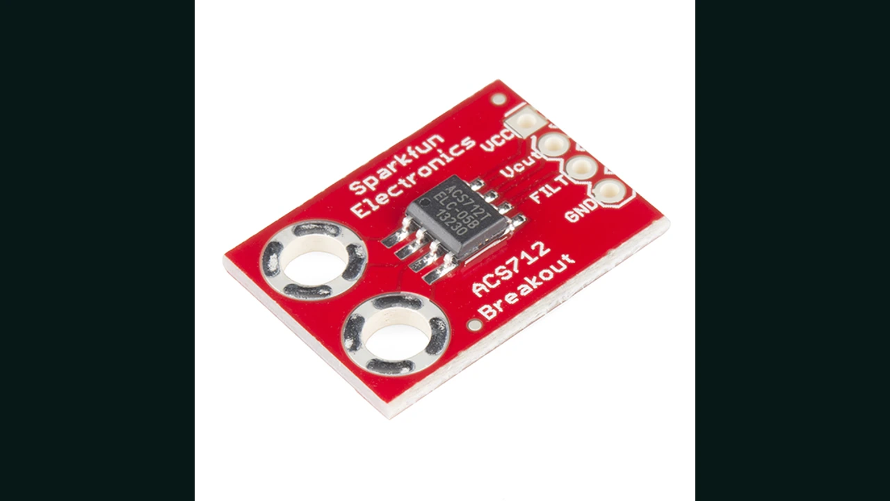

1. The purpose and actual application of the project
For experimental current monitoring of a small DC motor or benchtop resistive load, the ACS712 generates a voltage proportional to the current flowing through the conductor path. The result of this example is only a DC estimate on the serial monitor. This measurement is made with a load of 12 V or less and a current limit of 1 amp set in the bench power supply; This is our test ceiling, not the nominal specification of the sensor.
Measure background in Course of sensors in 7 steps and related topics in Pressure, weight and flow hub see
2. Reading the datasheet: x05B is different with 20 and 30 amps
In the Allegro official datasheet for the x05B grade, the optimal measurement range is from minus 5 to plus 5 amps and typical sensitivity at 5 volts is 185 mV/amp. x20A and x30A grades have different sensitivity; Do not use the number 185 for them. The power supply of the chip is 4.5 to 5.5 volts; In this example, we give the adjusted 5 volts to the module.
At zero amps, the output is roughly half VCC, ie about 2.5V at a nominal 5V supply. The chip datasheet does not guarantee the printed specifications, terminals and safety clearances of any ready-made miscellaneous module. Even if the chip has an isolation number, do not rely on it to connect these boards to the city electricity.
3. From voltage to amps
For a 5 amp at 5 volt grid, an example relationship is I ≈ (Vout - Vzero) / 0.185; Voltages are in volts. But we get Vzero from the actual data of the same module and the same power supply, in no current mode. Computational example, not our experiment: If Vzero is 2.500V and Vout is 2.685V, the current will be about 1 amp.
The output of the chip changes with power; In ESP32, measure the 5V voltage of the sensor under normal load with a multimeter and enter it in the code. This relationship is an educational starting point; The final accuracy can be measured only with a reference ammeter in a few specific currents.
4. Parts and tools
- ACS712 module 5 amp version, not raw IC or 20/30 amp module.
- Classic ESP32 or Uno R3, USB cable, laboratory DC supply with current limiter and low voltage load.
- Multimeter to control 5V, sensor output and ADC input; Reference ammeter for comparison.
- For ESP32, two resistors of 10 kOhm and 15 kOhm, and a capacitor of 100 nanofarads on the ADC input side.
The naming of the load terminals in ready-made boards is not the same. Start the setup by printing on the same board and its conductor path; The photo of the article is not the wiring diagram of the purchased product.
5. Low voltage wiring and output limiting for ESP32
Wire the module off and without load. Its VCC is set to 5V and GND is connected to the common ground. The path of the load flow must pass through the current terminals of the same board in series. First, check with a multimeter that VOUT is close to half of the supply at no load; Do not connect the 5V output directly to the ESP32 without this check.
| Connection | Classic ESP32 | Uno R3 | Tip |
|---|---|---|---|
| VCC module | 5 volts regulated | Check with a multimeter under normal load | |
| Module GND | common land | Do not confuse signal path and power | |
| VOUT module | 10 kΩ series to GPIO34; 15 kΩ from GPIO34 to GND | Straight to A0 | Measure the voltage before connecting |
| 100 nF capacitor | GPIO34 to GND, near board | It is not necessary in this example | This capacitor is on the ADC side, not the FILTER pin of the chip |
| load path | Series in protected DC circuit | Check product terminal labels | |
Dividing 10k/15k increases the output voltage to 0.6 times; For normal x05B output in the nominal range, the ESP32 input does not deviate from the selected ADC range. This network is not a protection against wiring error or connection of unknown voltages. Before any wire change, disconnect the load source and USB.
6. Why not convert the ESP32 raw value directly to voltage?
Espressif documentation differentiates between raw analogRead and calibrated analogReadMilliVolts. For classic ESP32, the ADC_11db setting has a documented range of about 150 to 3100mV. The program uses the same setting on GPIO34; ADC models S3 or C3 do not necessarily have the same behavior and pin.
On the Uno with the default reference and common 5V supply for the sensor, much of the supply variation is proportionally canceled out in the ADC reading. It is still necessary to zero and compare with an ammeter. The number of decimals on the serial number does not mean the actual accuracy of several decimals.
7. DC measurement code and zero calibration
At the moment of switching on, the current of the sensor path must be zero indeed. After three seconds, the program averages the 32 samples and sets it as the zero point. For ESP32, first change the value of SENSOR_SUPPLY_MV from zero to the measured supply value in millivolts; A zero intentionally disables the amp's output. Use the two code package and wiring guide; The serial rate is 115,200.
#include <Arduino.h>
#include "acs712_math.h"

#if defined(ARDUINO_ARCH_ESP32) && defined(CONFIG_IDF_TARGET_ESP32)
constexpr uint8_t SENSOR_PIN = 34; // Classic ESP32 ADC1.
// Measure the actual sensor supply with a meter under normal load, then set mV.
constexpr float SENSOR_SUPPLY_MV = 0.0f; // 0 deliberately disables current output.
#elif defined(ARDUINO_AVR_UNO)
constexpr uint8_t SENSOR_PIN = A0;
#else
#error "Use classic ESP32 or Arduino Uno R3; other ADCs need a fresh design."
#endif

constexpr int SAMPLE_COUNT = 32;
int32_t zeroReading = 0;
uint32_t lastReport = 0;

int32_t averagedInput() {
  uint32_t total = 0;
  for (int i = 0; i < SAMPLE_COUNT; ++i) {
#if defined(ARDUINO_ARCH_ESP32)
    total += analogReadMilliVolts(SENSOR_PIN);
#else
    total += analogRead(SENSOR_PIN);
#endif
    delay(4);
  }
  return (total + SAMPLE_COUNT / 2) / SAMPLE_COUNT;
}

void setup() {
  Serial.begin(115200);
#if defined(ARDUINO_ARCH_ESP32)
  analogReadResolution(12);
  analogSetPinAttenuation(SENSOR_PIN, ADC_11db);
#else
  analogReference(DEFAULT); // Uno ADC reference and sensor VCC must share 5 V.
#endif
  Serial.println(F("Remove primary current first; zero calibration starts in 3 s."));
  delay(3000);
  zeroReading = averagedInput();
  Serial.print(F("zero_ADC=")); Serial.println(zeroReading);
  Serial.println(F("DC low-voltage educational measurement only; no mains or protection use."));
}

void loop() {
  if (millis() - lastReport < 250) return;
  lastReport = millis();
  const int32_t reading = averagedInput();
  float amps;
#if defined(ARDUINO_ARCH_ESP32)
  if (SENSOR_SUPPLY_MV == 0.0f) {
    Serial.println(F("CONFIG_REQUIRED: measure 5 V sensor supply and set SENSOR_SUPPLY_MV."));
    return;
  }
  amps = currentFromAdcMv(reading, zeroReading, SENSOR_SUPPLY_MV);
  Serial.print(F("ADC_mV=")); Serial.print(reading);
#else
  // Both ACS712 output and Uno DEFAULT ADC reference track the same 5 V rail.
  // At nominal 5 V, x05B slope is 185 mV/A; ADC is 10-bit, 1024 levels.
  amps = (reading - zeroReading) * (5.0f / (1024.0f * 0.185f));
  Serial.print(F("raw=")); Serial.print(reading);
#endif
  if (!isfinite(amps)) {
    Serial.println(F(" supply/configuration invalid"));
    return;
  }
  Serial.print(F(" DC_A_approx=")); Serial.println(amps, 3);
}
A separate RAW sample shows the raw data to separate the wiring problem from the voltage-to-current conversion. In ESP32, its raw number and millivolts are separated from two conversions. The code output for DC is approximate; RMS does not calculate AC current or power.
8. Step-by-step test with reference
- First, identify the 5 amp model on the board and the path of the two current terminals. With the power off, close the load series connection.
- Set the test supply to the required DC voltage of the load, 12 V maximum, and a current limit of 1 amp maximum.
- At no load, measure VCC and VOUT with a multimeter. For ESP32, after resistive division, measure the GPIO34 voltage before connecting to the board.
- With no current in the sense path, turn the board on until zero registers. Then slowly activate the load.
- At several stable current values, compare the program number with the reference ammeter and record the difference. The direction of the current may change the sign of the output.
If the board gets hot, smells unusual, or results are unexpected, turn off the power supply. Do not use this guide for city wiring.
9. noise reduction; Find the cause first
The sensitivity is 185 mV/A at 5 V; So millivolt noise can be seen in the current reading. Check separately for long cable, improper ground, unstable source and external magnetic field. Averaging 32 samples reduces oscillation but does not correct static error, saturation, or circuit shape.
The FILTER base of the chip is in the datasheet to adjust the bandwidth, but don't guess its value and connection on the ready module without the schematic of the same product. The 100 nanofarad capacitor of this project, next to the ADC, is not a substitute for changing the module's internal filter. For fast pulse or RMS AC measurements you need a different design and sampling.
10. Troubleshooting irrational numbers
| sign | review | Allowable conclusion |
|---|---|---|
| At zero current, non-zero number | Was the current really zero? Did the temperature and nutrition change? | Record zero again at steady state |
| Relative difference in all streams | 5 amp or 20/30 amp version? Actual VCC and resistors? | Do not impose the wrong sensitivity on the code |
| Saturated or volatile reading | GPIO34 voltage, ground, load path and ADC setting | Do not conclude the sensor failure from the printed number alone |
| Reverse flow sign | To pass through the conductor path of the same module | The sign indicates the reference direction |
| CONFIG_REQUIRED | The value of SENSOR_SUPPLY_MV | Measure the feed and then adjust |
12. shopping in Iran; Exact model and inventory at review date
Direct inspection of product pages was done on 30 September 1405, equal to 09/21/2026. The subject of both links is the ACS712 module 5 amp version, not the raw SMD chip or the 20/30 amp version. Questions and practical opinions from buyers in ECA are indicative of practical application, not sales statistics or customer guarantees. No fixed price is listed because it may change.
| Detailed product page | type | Inventory at checkout |
|---|---|---|
| 5 amp current sensor module ACS712 in ECA | ready module; Code 3011007029 | existing |
| ACS712 5 amp current sensor module in solar computer | 5 amp ready module | non-existent |
Before ordering, check the board shape, module pins, chip etched grid and terminal power from the vendor. The Allegro datasheet tells the specs of the chip, not the build quality or originality of the shop module.
13. Common questions
Should we connect the output of ACS712 directly to ESP32?
No in this plan; The module operates at 5V and the output may be high for the GPIO. Resistive division and voltage measurement are required before connection.
Why do we see about 2.5 volts at no load?
In the bidirectional grid, the zero current output in the nominal 5V supply is close to half of the supply. This voltage does not mean 2.5 amps.
Should we read the 20 amp model with the same code?
No; The sensitivity of the 20 amp version is different from the 5 amp version. Read the chip model and use the datasheet of the same grade.
Is the output number valid for AC current or city power?
No; The code is only an estimate of the low voltage DC current. Chip isolation is not a ready board safety or city power connection permit.
Does averaging make the device a protective tool?
No; Averaging only reduces part of the fluctuation. Overcurrent protection should be independently designed and tested on real hardware.
14. Official sources and summary
- Allegro — ACS712 Datasheet: Grade x05B, Sensitivity, Zero, Power and Limits.
- Espressif — Arduino ESP32 ADC API: Reading millivolts and attenuation.
- Arduino — analogRead and analogReference: Reading ADC on Uno.
The next step is to tabulate your actual reference voltage and current data; Until then, refrain from making claims of accuracy or protective utility.
Question and answer article
Ask your technical question
Questions and answers are published after moderation. Authors can see their own pending drafts.
No confirmed questions have been registered for this article yet.