What is hysteresis? Stop a sensor alarm from chattering
Learn two thresholds and previous-state memory with a fictional temperature trace, code, invalid-data handling and the difference from filtering or delay.
Contents
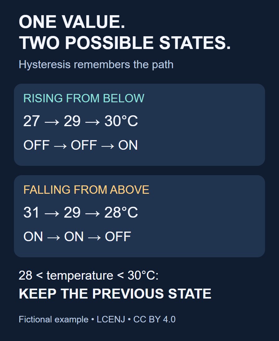
Suppose a temperature alarm should activate at 30°C. If the reading fluctuates near that value, a single-threshold rule can repeatedly switch the alarm on and off. A common solution is to use separate switching thresholds: activate at 30°C, but do not release the alarm until the temperature falls to 28°C. This separation between switching thresholds is hysteresis. It does not correct the measured temperature; it prevents small, repeated crossings of one boundary from repeatedly changing the alarm state.
Between the two thresholds, the result depends on the previous state. At 29°C, an alarm that was already active remains active, while an inactive alarm does not turn on. The current temperature alone is therefore insufficient: the program must also remember the alarm state. The 30°C and 28°C values are chosen to explain the idea, not to specify limits for a real device.
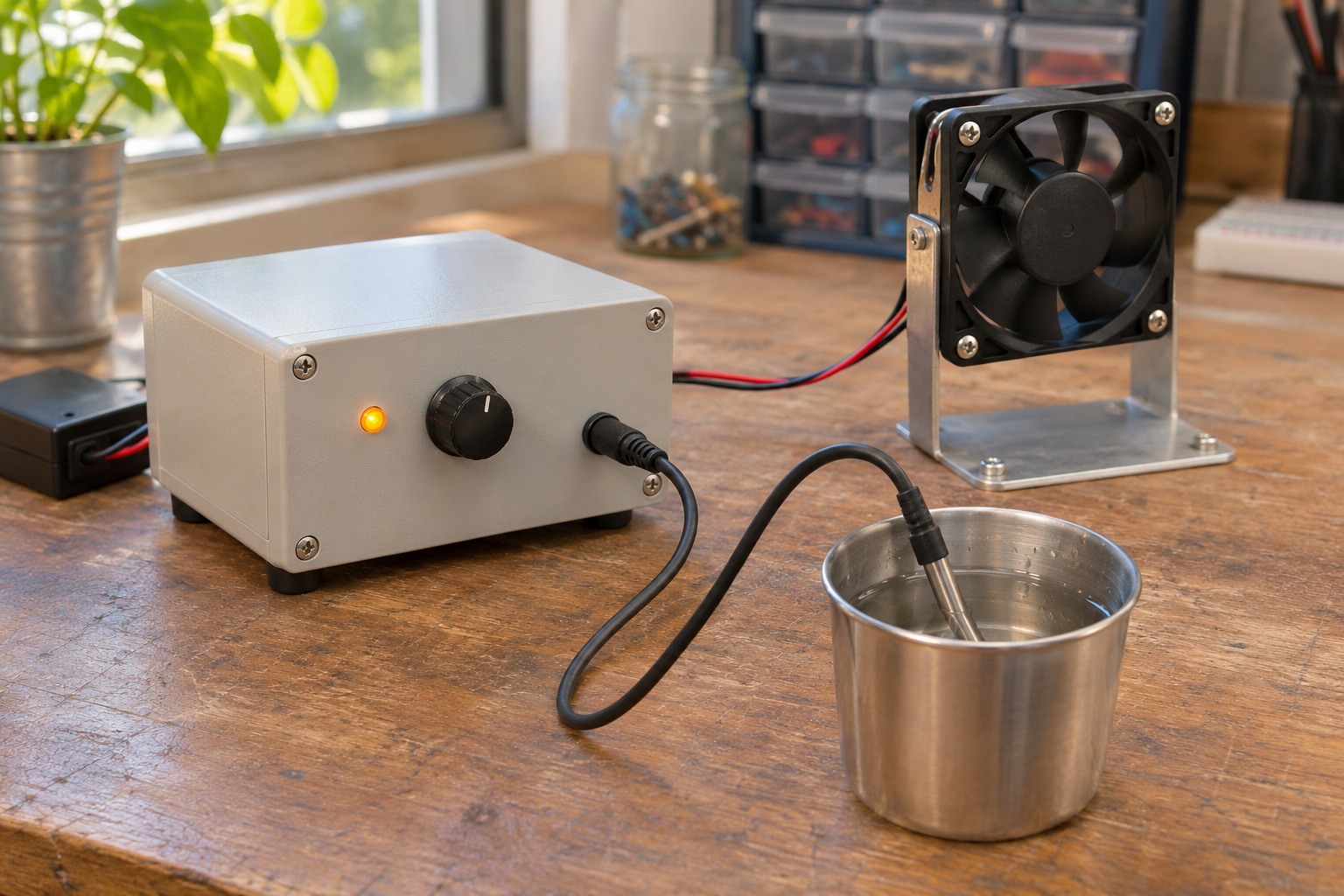
Why one threshold can be troublesome
A threshold is the value used to decide a state. Noise is an unwanted variation superimposed on the signal or its reading. With the rule “30 degrees or more means alarm,” readings of 29.9, 30.1, 29.8 and 30.2 degrees repeatedly switch the output, even if the underlying environment has changed very little. Such repeated transitions are often called chatter.
A fluctuating number is not necessarily noise: the environment may really be changing, or the sensor may be poorly located. Record readings with their times before choosing a remedy. Hysteresis should not conceal a supply, connection, calibration or sensor-placement problem. TI's discussion of comparator chatter explains repeated crossings close to a decision boundary.
Two thresholds and an explicit state
We will implement this software alarm below. Call the activation threshold H = 30°C and the release threshold L = 28°C. Their separation is H − L = 2°C, the hysteresis width. It is neither the sensor’s accuracy specification nor a time delay. Driving a fan or heater would also require the equipment’s operating conditions and protections to be designed separately.
- While the alarm is off, turn it on only at or above H.
- While the alarm is on, turn it off only at or below L.
- Strictly between L and H, leave the state unchanged.
Equality is deliberately included in both switching rules. Different comparison operators change behavior exactly at the boundaries. Also validate H>L before operation; a reversed or equal pair should not silently become an accepted configuration.
Follow one trace through the rules
The table applies these rules with the alarm initially off and every temperature assumed valid. Each row supplies a new input value; the table does not specify the time between readings. To follow the result, identify the previous state first, then evaluate the condition for that state. The accompanying file reproduces the same sequence.
| Fictional temperature, °C | Alarm after reading | Reason |
|---|---|---|
| 29.0 | Off | Has not reached 30 |
| 30.0 | On | Equals the upper threshold |
| 29.7 | On | Retain the state inside the band |
| 30.1 | On | Already active |
| 28.5 | On | Has not reached 28 |
| 28.0 | Off | Equals the lower threshold |
| 29.2 | Off | Now approaching from the inactive state |
For another trace—29.9, 30.1, 29.8, 30.2, 29.7 and 30.1—a single-threshold decision starting off changes state five times. With the two thresholds above, the same input activates the alarm once. This is a calculated result for that particular sequence, not a general claim about power savings, relay lifetime or a tested product.
A small function that keeps data validity separate
The Python 3 function below implements the alarm logic. Its temperature_c input is in degrees Celsius, and was_on carries the previous alarm state. The valid argument must indicate that the sensor read succeeded and the sample is usable; a communication failure must not be turned into a zero-degree reading. The code was executed with Python 3.12 using synthetic inputs, without a connected board. It does not cover every requirement of an equipment controller.
import math

def update_alarm(was_on, temperature_c, valid, low=28.0, high=30.0):
    if not (math.isfinite(low) and math.isfinite(high) and low < high):
        raise ValueError("invalid thresholds")
    if not valid or not math.isfinite(temperature_c):
        return was_on, False
    if was_on:
        return temperature_c > low, True
    return temperature_c >= high, True
The function returns two values: the alarm state and whether the current sample supports that decision. If the sample is invalid, this example retains the previous state and returns False as the second value. The application must report the fault separately: an alarm remaining on or off does not establish that measurement is working. The appropriate response to sensor loss depends on the application and might require stopping the device, disabling an output or raising a separate fault alarm.
At startup there is no previous state established from a fresh reading. If the first temperature is 29 degrees, the startup policy matters. Here, off is a chosen initial value, and validity remains false until a valid sample arrives. This is not a universal safety policy. After a power cycle, restoring a stored state is also insufficient without checking data freshness.
Filtering, hysteresis and delay do different jobs
Filtering, hysteresis and delay can be used together, but they solve different problems. A filter changes the data value—for example, replacing one temperature reading with an average. Hysteresis leaves the temperature unchanged and controls when the output switches state. Requiring consecutive samples or a specified dwell time adds a separate test of whether a condition has persisted long enough.
Each choice affects the device’s response. Stronger filtering can delay the appearance of a real change. Holding the activation threshold fixed while lowering the release threshold requires a larger temperature fall before the alarm clears. Requiring five consecutive samples makes response time depend on the actual sampling interval; reading a register five times does not necessarily obtain five fresh measurements. The two linked lessons below explain the relevant sampling and response-time issues.
sensor sampling lesson
real-time lesson
How should the width be chosen?
Begin with the behavior needed: at what temperature should the alarm activate, and when is release actually acceptable? Then examine valid readings under stable conditions, real environmental changes, measurement uncertainty and response constraints. If the measured excursions span the whole threshold gap, the output can still cycle. Hysteresis does not guarantee rejection of every kind of noise.
Do not move an activation limit merely to stop a blinking indication. If a maximum permitted temperature exists, sensor error, sampling delay and response time need separate design margins. Moving the release threshold farther away can also keep an alarm active longer than necessary. A fan or compressor may have an independent minimum on or off time; this lesson specifies neither its value nor its circuit.
The same principle also appears in hardware
The same principle appears in comparator circuits. A comparator compares its input voltage with a reference. Positive feedback can make the switching threshold depend on the current output state, producing two different thresholds. A Schmitt-trigger input likewise has separate thresholds for rising and falling transitions. The relationship between input direction and output state depends on circuit configuration; an inverting circuit must not be assumed to match this software alarm’s polarity. The manufacturer explanation linked below describes the mechanism.
Toshiba explains the two state-dependent thresholds
A buildable circuit needs the exact comparator, supply, input range, output type, load and resistor tolerances. The temperature example therefore does not determine resistor values or GPIO compatibility. Also distinguish the inherent hysteresis of some sensors—the different measurement curves while a quantity rises and falls—from the two thresholds deliberately added to alarm logic.
Exercise and verification
Start with the alarm on and follow readings of 29, 28, 29 and 30 degrees. The resulting states are on, off, off and on. Now insert an invalid reading between two samples: the function retains the state but returns False for validity. Download the logic calculation and checks and fictional example trace.
For a real investigation, log sample time, value, validity, previous state, new state and reason for transition. Check fluctuation near each boundary, exact equality, startup inside the band, invalid readings and power cycling separately. Here, the logic is evaluated on synthetic inputs.
Further reading: Analog Devices on comparator instability. This conceptual lesson does not recommend a particular purchasable part or board.
Question and answer article
Ask your technical question
Questions and answers are published after moderation. Authors can see their own pending drafts.
No confirmed questions have been registered for this article yet.